Siemens FCM-6, LCM-8, SCM-8 Desigo Modular Control Modules, data sheet

File Preview
Click below to download for free
Click below to download for free
File Data
| Name | siemens-fcm-6-lcm-8-scm-8-desigo-modular-control-modules-data-sheet-4630278951.pdf |
|---|---|
| Type | |
| Size | 1.02 MB |
| Downloads |
Text Preview
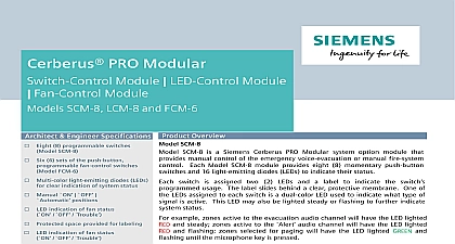
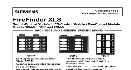
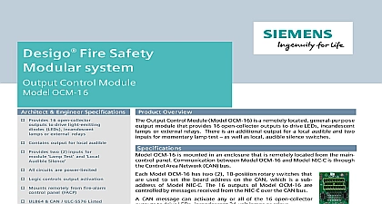
Fire Safety Modular Module LED Control Module Fan Control Module SCM 8 LCM 8 and FCM 6 Architect Engineer Specifications Eight 8 programmable switches SCM 8 Six 6 sets of the push button fan control switches FCM 6 Multi color light emitting diodes LEDs clear indication of system status Manual ON OFF positions LED indication of fan status OFF Trouble Protected space provided for labeling LED indication of fan status OFF Trouble Programmable LED annunciation Remote mounting in Model or REMBOX4 enclosures Supervised positive system feedback Protected label provided Modular Activation stagger timer UL864 CAN ULC S576 Listed FM NYCFD Approved Product Overview SCM 8 SCM 8 is a Siemens Desigo Fire Safety Modular system option module that manual control of the emergency voice evacuation or manual fire system Each Model SCM 8 module provides eight 8 momentary push button and 16 light emitting diodes LEDs to indicate their status switch is assigned two 2 LEDs and a label to indicate the switch s usage The label slides behind a clear protective membrane One of LEDs assigned to each switch is a dual color LED used to indicate what type of is active This LED may also be lighted steady or flashing to further indicate status example zones active to the evacuation audio channel will have the LED lighted and steady zones active to the Alert audio channel will have the LED lighted and flashing zones selected for paging will have the LED lighted GREEN and until the microphone key is pressed the zone transfer confirmation message is received by the Desigo Fire Safety system command console the LED will change to steady GREEN indicating it is clear to page Telephone zones with an incoming call in progress will have LED flashing GREEN until selected at the command console at which time the will change to steady GREEN etc This process allows the operator easy clear to the overall system condition at all times The second LED is AMBER and is to indicate a fault condition Model SCM 8 switch module is fully programmable and may be used to speaker circuits and a wide range of general system functions such as All All Evac Warden s Page Speaker etc Any number of circuits may be and controlled by a single switch Switch usage and zone groupings are using the Zeus D system programming software Model SCM 8 module is mounted on a hinged panel as a part of Desigo Fire Safety Modular system command console enclosure Model FCM 6 Module Module LCM 8 SCM 8 Module Sheet 7317 Technologies Division Product Overview continued LCM 8 is a Desigo Fire Safety Modular system option module that provides LED annunciation of system Each Model LCM 8 module contains eight 8 groups of two 2 LEDs each of which can be assigned to outputs using the Zeus D programming software Eight 8 LEDs are capable of being lighted either RED or flashing or steady The remaining LEDs are AMBER flashing or steady space is provided for labeling of LED functions The label slides behind a clear protective membrane Model LCM 8 are identical to Model SCM 8 and Model LCM 8 is mounted on the same hinged panel as a part of the Desigo Fire Modular system command console enclosure Any combination of Models SCM 8 and LCM 8 modules may be used FCM 6 is a Desigo Fire Safety Modular system command console option module that provides manual of building heating ventilation air conditioning HVAC system fans and dampers Each Model FCM 6 provides six 6 sets of three 3 push button switches for manual system control Each switch has three associated LEDs to indicate Fan Damper status OFF RED LED ON GREEN LED TROUBLE YELLOW LED in the automatic position the RED and GREEN LEDs indicate Fan Damper status ON OFF on the system logic that can be programmed to automatically control the fan outputs manually switched to the OFF position the RED LED will flash indicating the output circuit used to turn off the Damper has activated The RED LED will light a steady stream of RED to indicate positive feedback of the Fan actually turning off via a monitored input When manually switched to the ON position the GREEN LED will indicating the output circuit used to turn on the Fan Damper has activated The GREEN LED will light to a steady to indicate positive feedback of the Fan Damper actually turning on via a monitored input RED Solid GREEN Solid Flashing Solid Flashing Solid on System Logic Driving Outputs Sent to Turn On Outputs is ON Feedback Received that output is powered On Sent Out to Turn Off Outputs Feedback Received that output is turned Off is OFF system reset when switches have been manually set to the ON or the OFF position their outputs do not change state The switches stay either ON or OFF based on the position of the Outputs will only change state when manually controlled via the ON OFF switch or based on logic when switch is in the Auto position Model FCM 6 module is mounted on a hinged panel as a part of the Desigo Fire Safety Modular system console enclosure Any combination of Model SCM 8 Model LCM 8 or Model FCM 6 modules may be on the inner door mounting plate Model ID MP A six conductor cable is supplied for interconnection the modules A 30 inch 76.2 cm cable Model CCL is available for connection between rows SCM 8 LCM 8 and FCM 6 may be remotely mounted up to 1,000 feet 305 meters from the main The Model REMBOX2 and REMBOX4 lobby enclosures are required for remote mounting of a SCM 8 LCM 8 and FCM 6 The CAN sounder board Model CSB is optionally available for audible for remote mounting applications and Humidity Range are UL 864 9th Edition Listed for indoor dry locations within a temperature range of 120 3 49 2 32 3 0 2 and a relative humidity of 93 2 at a temperature of 90 3 32 2 Technologies Division for Ordering TYPE 500 033140 Fan Control Module Switches OFF AUTO 500 033100 Annunciator Module 8 LED sets 500 033040 Module 8 switches Plate Cable Feet 0.91 Meter Long Sounder Board Door Mounting Plate up to four 4 modules Ratings Current Draw Plane Current Draw Terminal Current Draw Plane Current Draw Max 1mA active LED Max 1mA active LED Technologies Division NOTICE The information contained in this data sheet document is intended only a summary and is subject to change without notice product s described here has have a specific instruction sheet s cover various technical limitation and liability information of install type instruction sheets as well as the


