Siemens FCM20xx-U2, FCM20xx-U3 Operating unit, Operating unit (+ LED), Installation Instructions

File Preview
Click below to download for free
Click below to download for free
File Data
| Name | siemens-fcm20xx-u2-fcm20xx-u3-operating-unit-operating-unit-led-installation-instructions-7243691850.pdf |
|---|---|
| Type | |
| Size | 1.97 MB |
| Downloads |
Text Preview
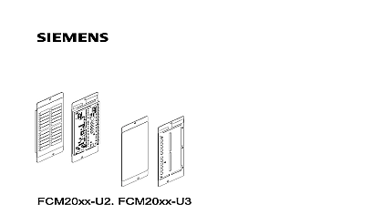
FCM20xx U3 unit unit LED Industry Inc Technologies Division notice notice specifications and availability subject to change without notice 2013 Copyright by Siemens Industry Inc reproduction dissemination and or editing of this document as well as of its contents and communication thereof to others without express are prohibited Offenders will be held liable for payment of damages All created by patent grant or registration of a utility model or design patent are by Industry Inc Technologies Division Fernwood Road Park NJ 07932 1 973 593 2600 2013 06 04 ID A6V10315030 b en Industry Inc Technologies Division of contents unit FCM20xx 4 4 and wiring the operating unit 6 of PMI mainboard 9 10 elements 11 data 12 module and LED module red yellow yellow 13 13 14 elements 15 data 16 Statement 17 Industry Inc Technologies Division unit FCM20xx Operating unit FCM20xx of FCM2018 operating unit of FCM2019 and FCM2035 operating unit LED Description operating unit is installed in the panels and comes in three versions FCM2018 operating unit with control and display elements FCM2019 operating unit LED with extra integrated LED module FCM2035 operating unit LED with extra integrated LED module operating unit has an integrated PMI mainboard FCM2027 with the CPU MPC8248 and the expansion slots Industry Inc Technologies Division unit FCM20xx 1 Ground fault supervision for system supply detected at 1 k cid 726 real time clock Maintains the time function for at least two days in the of power failure to the periphery board Shield plate Slot for a network module SAFEDLINK with full functionality Ethernet connection for maintenance PC 2 slots for serial options RS485 class A module for connecting additional devices external printer or strips for sliding in Peripheral data bus connection for LED module Retainer for the license key Person Machine Interface has the following features Graphic compatible display 8 lines Buzzer Configurable LED indicators Operating buttons Operation can be released with a password or key switch optional functions of FCM2019 operating unit LED 24 zone indicator with LEDs A bicolored LED per zone red green A yellow LED per zone of any events functions of FCM2035 operating unit LED 24 zone indicator with LEDs A bicolored LED per zone red yellow A yellow LED per zone of any events references templates for the inscription strips and the operating instructions with button and designations have the following document IDs PRO strips Operation strips will find detailed information about the LED module in the chapter LED module LED module red yellow yellow cid 4550 13 Industry Inc Technologies Division unit FCM20xx and wiring the operating unit Mounting and wiring the operating unit chapter describes how to install the operating unit on the inner door Installation wiring of all operating units is identical operating unit can also be installed on the outer door in place of the clear glass the operating unit the operating unit on the inner door rear view door with window FHD2004 unit FCM20xx fixing nut for operating unit set screw for operating unit welded steps Plug the operating unit 2 onto the set screws 4 of the inner door 1 from behind shown above Use the four nuts 3 to screw the operating unit tight Industry Inc Technologies Division unit FCM20xx 1 and wiring the operating unit the operating unit the FCM2018 operating unit inside view of the operating unit LED fastenings of operating unit to modules of operating unit rail kit FHA2031 bus connection on periphery board X201 cable fixing with cable support data bus connection on PMI mainboard X3 door with FCM2018 operating unit data bus connection output X402 to further LED modules or option module data bus connection input for LED module X400 wired at the factory door with operating unit LED Industry Inc Technologies Division unit FCM20xx and wiring the operating unit the connection cable to the periphery board into the intended slots 4 and 6 Stick the supplied cable supports 5 into the panel as shown and fix the flat cable Guide the cables for the operating unit modules 2 to the DIN rail kit 3 as shown fix these cables with cable ties the supplied inscription strips underneath the operating unit film as shown in figure below Swivel the inner door towards the panel and secure it using the locking screw the inscription strips the inscription strips into the operating unit LEDs for the standard keys in the center for standard keys on the right for LED module depending on whether operating unit is present or not for panel and alarm Industry Inc Technologies Division View of PMI mainboard unit FCM20xx 1 of PMI mainboard for PMI mainboard FCM2027 Industry Inc Technologies Division unit FCM20xx connections keys H61 plate for key switch T45 for periphery board or fire terminal board supply and data connection for network module SAFEDLINK FN2001 for RS485 class A module isolated FCA2016 used for RS485 class A module isolated FCA2016 for peripheral data bus indicators key for ground fault supervision of the Ethernet connection for license key for ground fault supervision of the system supply