Siemens FDBZ492, FDBZ492-R and FDBZ492-HR Air Duct Monitoring Housings, Installation Instructions

File Preview
Click below to download for free
Click below to download for free
File Data
| Name | siemens-fdbz492-fdbz492-r-and-fdbz492-hr-air-duct-monitoring-housings-installation-instructions-7610824539.pdf |
|---|---|
| Type | |
| Size | 788.87 KB |
| Downloads |
Text Preview
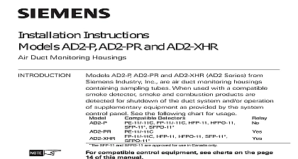
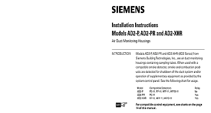
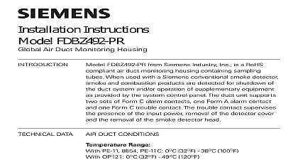
Installation Instructions FDBZ492 FDBZ492 R and FDBZ492 HR Duct Monitoring Housings DATA DUCT CONDITIONS FDBZ492 FDBZ492 R and FDBZ492 HR from Siemens Industry Inc are air monitoring housings containing sampling tubes When used with a compatible detector smoke and combustion products are detected for shutdown of the system and or operation of supplementary equipment as provided by the control panel See the following chart for usage see charharharharharts on page 1 compat compat compat control equipment control equipment see c see c on page 1 on page 1 of this manual of this manual on page 11 of this manual control equipment see c compatible control equipment of this manual on page 1 see c control equipment compat of this manual Range FP 11 11C HFP 11 HFPO 11 SFP 11 SFPO 11 8854 8710 8713 OOHC941 32OF 0OC 100OF 38OC per UL 268 FDOOT441 OOH941 FDO421 OP921 32OF 0OC 120OF 49OC per UL 268 Range FDBZ492 R and FDBZ492 HR No altitude limitations Humidity Range non condensing non freezing Duct Velocity Range ft min FDBZ492 FDBZ492 R and FDBZ492 HR Tube Pressure Range of Differences than 0.01 and less than 1.2 inches of water column air duct detectors are designed for detection and control of products of are not to be used for are not to be used for open area prot open area prot open area protectectectectection in a duct system They are not to be used for are not to be used for open area prot are not to be used for open area prot NOT USE air duct detectors with Alarm Verification SFP 11 and SFPO 11 are approved for use in Canada only Inc Inc Inc Industry Inc Inc Infrastruct Infrastructureureureureure Infrastruct Infrastruct Infrastruct detector has a cover tamper removal switches Care should be taken when the cover Squarely place the cover on the unit to aviod possible damage to switches NOT SLIDE COVER INTO POSITION duct smoke detectors provide early detection of smoke and products of combus present in air moving through an HVAC duct supply return or both These are designed to prevent the recirculation of smoke in areas by the air system fans and blowers Complete systems may be shut down in the of smoke detection the correct installation of a duct smoke unit please refer to NFPA 72 National Alarm Code NFPA 90A Standard for Installation of Air Conditioning and Systems and NFPA 92A Recommended Practice for Smoke Control the Models FDBZ492 FDBZ492 R and FDBZ492 HR are operating a sample air is drawn from the duct and passed through the sampling chamber by means of input sampling tube The air sample passes through the smoke detector mounted the duct housing and is exhausted back into the duct through the outlet tube detector is equipped with cover removal switches SW1 SW2 that instantly a trouble condition upon removal of the clear cover For all testing and with the cover removed the cover removal switches designated as SW1 on PCB must be manually depressed to simulate normal operation Indicator FDBZ492 FDBZ492 R and FDBZ492 HR contain an LED indicator located on the detector capable of flashing either one of three distinct colors green yellow or During each flash interval the microprocessor based detector checks the following smoke in its sensing chamber its critical smoke sensing electronics are operating on the results of these checks the LED indicator flashes as follows OP121 FDO421 OP921 FDOOT441 FDOOTC441 OOH941 OOHC941 detectors are not serviceable and need replacement Industry Inc Infrastructure A CLOSED SYSTEM NO EXHAUST AIR INTAKE DUCT DUCT B PROVISION FOR EXHAUSTING PERCENTAGE OF RETURN AIR AIR INTAKE AIR DUCT DUCT C RETURN AIR UNDER POSITIVE PRESSURE SEPARATE BLOWER AIR INTAKE AIR AIR DUCT DUCT 2 Locations in Duct Systems DUCT 1 Mounting of Duct Housing THE AIR DUCT HOUSING on Duct System guideline contains general information on duct smoke detector installation but not preclude the NFPA documents listed Siemens Industry Inc assumes no for improperly installed duct detectors To determine the correct installa position for a duct smoke detector the following factors must be considered uniform non turbulent laminar airflow between 100 ft min to 4,000 ft must be present in the HVAC duct To determine duct velocities the engineering specifications that define the expected velocities use an Alnor model 6000AP velocity meter or equivalent minimize the impact of air turbulence and stratification on performance a smoke detector should be located as far as possible downstream from obstruction i e deflector plates elbows dampers etc In all situa confirmation of velocity and pressure differential within specifications required pressure differential between the input sampling high pressure tube outlet low pressure tube for the smoke duct detector should be than 0.01 inches of water and less than 1.2 inches of water a code compliant location supply or return side or both for the of the duct unit that will permit easy access for viewing and When installing on the return side install duct units prior to the air being from the building or diluted with outside air Industry Inc Infrastructure Preparation Air Duct Housings come with an installation kit that contains the following items When installing duct smoke units downstream of filters fires occurring in filters will be detected but if the filters become blocked insufficient air through the duct unit will prevent the correct operation of the duct Duct units installed in the supply air side may monitor upstream and or filters Where possible install duct detectors upstream of air humidifiers and of dehumidifiers prevent false alarms the duct detector should not be mounted in areas extreme high or low temperatures in areas where high humidity exists in areas where the duct may contain gases or excessive dust return outlet sampling tube 12 x 3 4 sheet metal screws Mounting template packaged separately mounting template from the installation kit Remove paper backing from the template and affix it to the duct at the desired location Using the template a guide drill 2 mounting holes 3 32 2.5mm for the 12 X 3 4 sheet metal packaged in the installation kit Drill or punch 2 1 32mm holes for input and outlet tubes using the template as a guide Clean all holes duct smoke detectors use a specially notched sampling tube which may be separately in one of four standard lengths This model is supplied as two 5 ft sections with a coupling duct widths of 6 to 1.0 duct widths of 1.0 to 3.0 duct widths of 3.0 to 5.0 requires support duct widths of 5.0