Siemens FDT421 Heat Detector, Installation Instructions

File Preview
Click below to download for free
Click below to download for free
File Data
| Name | siemens-fdt421-heat-detector-installation-instructions-5984301672.pdf |
|---|---|
| Type | |
| Size | 741.33 KB |
| Downloads |
Text Preview
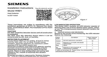
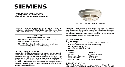
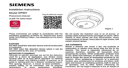
Figure 1 INDICATOR OPERATION Model FDT421 contains an LED indicator capable of either one of three distinct colors green yellow red The microprocessor based detector monitors the on the results of the monitoring the LED indicator the following sensors and electronics Interval supervisory operation is in trouble and needs is not powered or is needed LED can be turned off Please follow the corresponding of the Panel used Instructions FDT421 Detector listed for electronic version instructions are written in accordance with the guidelines of NFPA 72 National Fire Alarm and CAN ULC S524 The Installation of Fire Alarm NOT install this detection device until all construction completed NOT store this detection device where it can be by dirt dust or humidity PLACEMENT Model FDT421 on the ceiling at least 4 inches the side walls For an ideal smooth ceiling place the detectors at a maximum center of 50 feet 2500 square feet job conditions must determine detector spacing environmental factors including ambient fluctuation and the nature of the fire Room or area configuration and ceiling type or flat smooth or beamed also dictates provided or approved by Siemens Industry or by its authorized distributors are extremely The detector placements shown on these were chosen after a careful evaluation of the that is protected Siemens Industry Inc experience in the design of the system the best detector placement by following these Sound engineering judgment by qualified must be followed HUMIDITY PRESSURE temperature range for the FDT421 detector is 32 to 100 38 The thermal alarm temperature on the parameter selected Use the detector in where the humidity does not exceed 95 Normal changes of atmospheric do not affect detector sensitivity Industry Inc Infrastructure PROGRAMMING detector must be programmed to respond to an between 001 252 program the detector address use the Model DPU Programming Unit Refer to the DPU Manual P N the loop and device number system address for detector on the detector label and on the base to installing the detector in the wrong base The DPU label printer can be used for this purpose detector provides pre programmed parameter sets can be selected by the panel Follow the description of the panel used temperature 135 57 temperature 145 63 temperature 155 68 temperature 165 74 temperature 174 79 detection 15 8.3 at fixed 135 57 15 8.3 at fixed 174 79 the detector can be configured by some to have a low temperature warning at 40 FDT421 supports two operation modes polarity mode and isolator mode The Detector can be for either mode refer to Figure 2 and 3 During isolator mode the built in dual isolators will work at sides of the Detector to isolate the line short in front behind the device the FDT421 is wired in polarity insensitive mode 6 and 5 can be either line of the loop the FDT421 is wired for Isolator mode the positive needs to be connected to 1b and the negative line to The next device needs to be connected to 1b and 5 Line Isolator is located between connector 6 and 5 that the panel supports Isolator mode for FDT421 product version 17 mode must not be used with a FDT421 version 17 You will find the product number on the detector label 17 MOUNTING ensure proper installation of the detector head into the be sure the wires are properly dressed at Position all wires flat against the base Take up all slack in the outlet box Route wires away from connector terminals INSTALL DETECTOR HEAD Rotate detector counterclockwise while gently on it until the detector seats fully into base rotate the detector clockwise until it stops and in place Insert optional locking screw Order LK 11 REMOVE DETECTOR HEAD locking screw if installed Then rotate the counterclockwise until stop is reached Pull detector out of base TESTING qualified service personnel should test To assure operation of the detector the Functional Test be conducted The minimum test schedule may current edition of NFPA 72 for in the U S detectors can be tested individually using the DPU to the DPU Manual P N 315 033260 special maintenance procedures are required for the The control unit automatically indicates the message for any detector The detector may replacement no circumstances is the detector head to be repairs should be attempted NOT PAINT detector is marked DO NOT PAINT This is intended prohibit painting during routine maintenance of the which can affect proper operation of the FDT421 is a polarity insensitive detector Line 1 and Line 2 can be either line of the loop The relay contacts are shown after System reset which represents the non alarm condition insensitive wiring 1 BASE DB 11 DB 11E INITIATING CIRCUIT SIEMENS COMPATIBLE UNIT 8727C RL HC 2 2 mode wiring 1 initiating circuit of compatible control unit BASE DB 11 DB 11E 8727C RL HC 2 3 NEXT BASE NOT USE AN OF LINE DEVICE CONTACTS 120 VAC 30 VDC NOT USE AN OF LINE DEVICE NEXT BASE NEXT BASE NOT USE AN OF LINE DEVICE 120 VAC 30 VDC NOT USE AN OF LINE DEVICE NEXT BASE The relay contacts are shown after System reset which represents the non alarm condition size maximum 14 AWG minimum 18 AWG Wire larger than 14 AWG can damage the connector the device line up to 30 of any compatible devices in insensitive mode with 20 ohms max line can be isolated between two modules in mode in a Class A Style 6 wiring the device line up to 30 of any compatible devices in insensitive mode with 20 ohms max line can be isolated behind one module in isolator in a Class B Style 4 wiring Statement isolator module and SBGA 34 sounder base be used in the same loop with the modules in mode and usage of equipment not in accordance with instructions manual may in of radio frequency energy to radio communications Read the following information and use equipment in accordance with installation instructions manual equipment generates uses and can radiate radio frequency energy and if not installed and used in with the instructions manual may cause interference to radio communications has been tested and found to comply with the limits for a Class A computing device pursuant to Part 15 of FCC which are designed to provide reasonable protection against such interference when operated in a environment of this equipment in a residential area is likely to cause interference in which case the user at his own will be required to take whatever measures may be required to correct the interference Industry Inc Infrastructure Fernwood Road Park New Jersey 07932 Canada Limited Infrastructure Kenview Boulevard Ontario L6T 5E4 A5Q00041075 Siemens Industry Inc and design subject to change without notice