Siemens FH2071-UM Enclosure, Installation Instructions

File Preview
Click below to download for free
Click below to download for free
File Data
| Name | siemens-fh2071-um-enclosure-installation-instructions-0753942618.pdf |
|---|---|
| Type | |
| Size | 812.61 KB |
| Downloads |
Text Preview
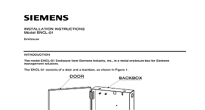
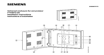
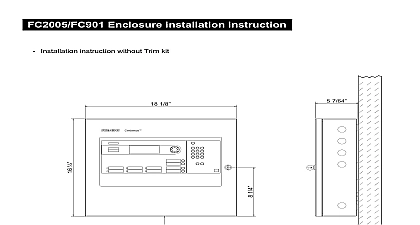
INSTRUCTIONS FH 2071 UM Enclosure Model FH 2071 UM Enclosure from Siemens Industry Inc used in Marine applications is and weather resistant Its durable design is customized for Marine installations due to the oceanic environment the equipment will regularly encounter 1 FH 2071 UM with Isolation Mounts OF FH 2071 UM ENCLOSURE Fully gasket sealed outer door Draw latches for secure closure Wire braided corrosion resistant vibration isolators Battery bracket that holds two 2 16AH batteries Built in EMI filter Built in AC Power Terminal additional information on compatible marine devices and applications refer to the Fire Alarm Control Panel Marine Application manual Document ID Technical Support at 1 800 248 7976 or support us i bt siemens com for marine issues Siemens Industry Inc Building Technologies Division 2 FH 2071 UM Enclosure Supplied Outer Door Backbox enclosure Filter Power Terminal Block Bracket LOCATION FH 2071 UM Enclosure is used for indoor damp locations mount the enclosure consider the following Mounting height for visual and manual access to the Weight and size of the enclosure Local mounting codes en b Industry Inc Technologies Division the Hold the empty enclosure against the wall at height that provides easy Mark drill points on the wall in the center of the two keyholes slots in Figure 3 on the upper rail that are attached to the Drill the two holes Screw in the top bolts user supplied leaving a small between the wall and each top bolt Mount the enclosure rail assembly on the two bolts Mark drill points on the wall for the remaining six holes in the rails Drill the bolts in the remaining two holes in the top rails and four holes in the rails Tighten all bolts securely conduits or cable with a maximum diameter of inch and a mininum of 18 inches from a rigid connection should be used to house external 3 FH 2071 UM Enclosure Mounting Dimensions en b Industry Inc Technologies Division All wiring must comply with local and national codes and use twisted pair wiring compliance with NEC Article 760 all power limited fire protective signaling must be separated a minimum of inch from all of the following located with a control panel Electric light Power Class 1 or non power limited fire protective signaling conductors meet these requirements the following guidelines must be observed installing modules and wiring to this control panel installing power limited field wiring the installer must comply with article 760 which states fire alarm power limited circuits are installed using Types FPL FPLR or permitted substitute cable provided these power limited cable extending beyond the jacket are separated by a minimum of in 6.35 mm or by nonconductive sleeve or nonconductive barrier all other conductors entering the enclosure from the right side is considered non power wiring Wiring must be in the shortest route and must not overlap any wiring Limited Wiring entering the enclosure from the left side is considered power limited must be in the shortest route and must not overlap any other wiring Drill and attach conduit fittings in the enclosure for the entry of field Only marine approved liquid tight conduit fittings are to be Pull all field wiring into the enclosure Do not dress the wiring until location of all the equipment is known the wiring from external power source to the approximate of the power supply See Figure 4 for details Entering Enclosure Limited Wiring Wiring primary mains input must have a separate or dedicated circuit breaker in accordance with local codes and NEC 760.0 en b Industry Inc Technologies Division WATTS SUPPLY LUG FILTER POSITION THE AC LINE BLOCK 4 Knockout Position for the AC Line THE ELECTROMAGNETIC INTERFERENCE EMI FILTER TO POWER SUPPLY Electromagnetic Interference EMI Filter is used to filter out noise that is created by the power supply 5 EMI Filter wiring Power Supply 170 Watts Neutral Wire Ground Lug Ground Wire AC Line en b Hot Wire 2 Position Terminal Block Industry Inc Technologies Division EMI Filter reduces the noise that is generated from the FS20 panel Refer to the Structure Panel image in section 5 for location of the filter The Neutral and Hot wire is connected to the two position terminal that is fed to the EMI filter Blue and Brown wire The Ground wire is plugged into the Ground Lug which is then to the Power Supply 170W FP2011 U1 FILTER Current Voltage VAC Frequency Hz Recognized CSA Certified VDE Approved Dimensions x 6 5 16 D x 30 5 8 H lbs GA 060 1008 or 1010 cold rolled steel phosphating treatment powder coating Black en b Industry Inc Technologies Division security disclaimer products and solutions provide security functions to ensure the secure operation of building comfort safety security management and physical security systems The security functions on these products and are important components of a comprehensive security concept is however necessary to implement and maintain a comprehensive state of the art security concept that customized to individual security needs Such a security concept may result in additional site specific action to ensure that the building comfort fire safety security management or physical security for your site are operated in a secure manner These measures may include but are not limited to networks physically protecting system components user awareness programs defense in depth additional information on building technology security and our offerings contact your Siemens sales or department We strongly recommend customers to follow our security advisories which provide on the latest security threats patches and other mitigation measures http www siemens com cert en cert security advisories htm en b Industry Inc Technologies Division This page has been left intentionally blank ID A6V10423703 en b Siemens Industry Inc A5Q00061442 Building Technologies Division