Siemens FN2006-U1 and FN2007-U1 Cerberus PRO Single-Mode Multi-Mode Fiber-Optic Module, Data Sheet

File Preview
Click below to download for free
Click below to download for free
File Data
| Name | siemens-fn2006-u1-and-fn2007-u1-cerberus-pro-single-mode-multi-mode-fiber-optic-module-data-sheet-8036129457.pdf |
|---|---|
| Type | |
| Size | 783.05 KB |
| Downloads |
Text Preview
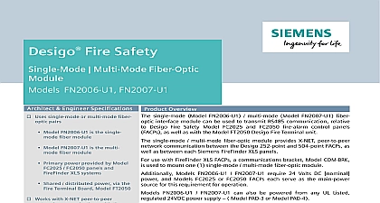
Cerberus PRO Multi Mode Fiber Optic FN2006 U1 FN2007 U1 Architect Engineer Specifications Uses single mode or multi mode fiber pairs Model FN2006 U1 is the single fiber module Model FN2007 U1 is the multi mode module Primary power provided by Model FC924 panels and XLS systems Shared distributed power via the Terminal Board Model FT924 Works with X NET peer to peer communications with the Generation Network Ring Card NRC 4 or 7 communication Fully supervised Operates in a daisy chain configuration UL 864 10th Edition Listed ULC S527 Edition Listed FM 3010 CSFM 7165 0067 0259 NYCFD 6104 Approved Infrastructure Building Products Product Overview single mode Model FN2006 U1 multi mode Model FN2007 U1 fiber interface module can be used to transmit RS485 communication relative Cerberus PRO Model FC922 and FC924 fire alarm control panels FACPs as as with the Model FT924 Cerberus PRO Fire Terminal unit single mode multi mode fiber optic module provides X NET peer to peer communication between the Cerberus PRO 252 point and 504 point systems as well as between each Siemens FireFinder XLS FACP use with FireFinder XLS FACPs a communications bracket Model COM BRK used to mount one 1 single mode multi mode fiber optic module Models FN2006 U1 FN2007 U1 require 24 Volts DC nominal and Models FC922 or FC924 Cerberus PRO FACPs each serve as the main source for this requirement for operation FN2006 U1 FN2007 U1 can also be powered from any UL Listed 24VDC power supply Model PAD 3 or Model PAD 4 Single Multi Mode Fiber Optic Module is FM 3010 CSFM 7165 and FDNY 6104 Approved Specifications FN2006 U1 FN2007 U1 each mounts in Cerberus PRO one height unit or two height unit 2HU enclosures and operates in a daisy chain The connection between single mode fiber optic modules uses 2 high quality duplex 9 125 fiber optic cables and fiber Model FN2007 U1 two 2 high quality duplex 50 125 or 62.5 1 25 cables via fiber connectors are used The two 2 cables are a single shield similar to an electrical zip cord fiber type 50 125 each segment of the fiber network can stretch up to 6,550 1.24 miles 2 km For both single mode multi mode installations overall system fiber is limited by the communication delay the entire fiber network Total network should not exceed 131,000 feet 24.8 40 km networked Cerberus PRO panel or terminal one 1 duplex cable for connection to Cerberus PRO panel FN2007 U1 Fiber Optic Sheet 9814 Specifications cont B installations each FACP or terminal at either end of the daisy chain uses one 1 duplex cable for connection the next networked panel or terminal Terminals or FACPs within the daisy chain requires two 2 duplex cables one duplex cable for connection to the previous FACP and one 1 duplex cable for connection to the next FACP A installations each FACP or terminal requires two 2 duplex cables one 1 duplex cable for connection to previous FACP and one 1 duplex cable for connection to the next FACP fiber optic module contains five 5 light emitting diode LED indicators for system power and system status Power LED is green and lights whenever there is 24VDC Both channels A and B have a yellow and green LED The LED indicates either the single mode or multi mode module is transmitting data on that channel The yellow LED when data is received Temperature and Humidity Range FN2006 U1 and FN2007 U1 are UL 864 10th Edition Listed for indoor dry locations within a temperature range 120 3 49 2 to 32 3 0 2 and a relative humidity of 93 2 at a temperature of 90 3 32 2 Data Connection Type of Fibers Between 2 Interface Modules Converter Two 2 Stations Length Station Optic Cable Fiber 50 125 Optic Cable Fiber 62.5 125 Optic Cable Fiber 9 125 feet m feet m feet m feet m Properties FN2007 U1 W x H x D 4.5 1.25 cm x 11.4 cm x 3.2 cm Lbs 576 g for Ordering MODEL module module Bracket FireFinder XLS enclosures Documentation Sheet Number Terminal Equipment PRO 252 point FACP PRO 504 point FACP Power Supply PAD 3 Power Supply PAD 4 Ring Card Generation Infrastructure Building Products NOTICE The information contained in this data sheet document is intended only as a and is subject to change without notice product s described here has have a specific instruction sheet s that cover technical limitation and liability information of install type instruction sheets as well as the General Product and Limitations document which also contains important data are with the product All are available from the Manufacturer contained in the aforesaid type of documentation should be consulted with a professional before specifying or using the product PRO problems that might arise relative to the functioning of the equipment please contact Manufacturer Any further questions or assistance concerning Industry Inc Technologies Division Fernwood Road Florham Park NJ 07932 973 593 2600 2022 6