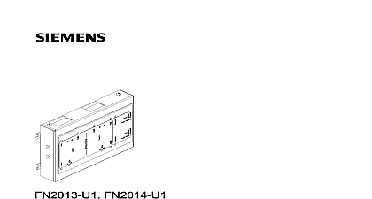
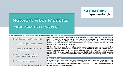
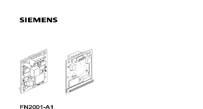
Siemens FN2006-U1 Fiber network module (SM), FN2007-U1 Fiber network module (MM)

File Preview
Click below to download for free
Click below to download for free
File Data
| Name | siemens-fn2006-u1-fiber-network-module-sm-fn2007-u1-fiber-network-module-mm-6239814750.pdf |
|---|---|
| Type | |
| Size | 1.72 MB |
| Downloads |
Text Preview
FN2006 U1 FN2007 U1 network module SM FN2006 U1 network module MM FN2007 U1 Technologies Industry Inc notice notice specifications and availability subject to change without notice reproduction dissemination and or editing of this document as well as of its contents and communication thereof to others without express are prohibited Offenders will be held liable for payment of damages All created by patent grant or registration of a utility model or design patent are by Industry Inc Technologies Division Fernwood Road Park NJ 07932 1 973 593 2600 2017 05 03 ID A6V10315048 d en Siemens Industry Inc 2015 22 Technologies Industry Inc of contents network module FN2006 FN2007 5 Description 5 in Desigo Cerberus PRO 6 in XLS 7 Views 8 Wiring 9 for Desigo Cerberus PRO 9 for XLS 13 supply sockets 4 6 16 for FCnet C WEB SAFEDLINK lines 7 8 17 18 Technical data 19 Statement 20 Technologies Industry Inc 22 of Figures 1 Installing the fiber network module FN2006 or FN2007 in the housing 2HU 6 2 Views of the fiber network module from above and the side 8 3 Wiring of fiber network module in fire control panel or fire voice control panel 9 4 Wiring example of optical network class A with four fiber network modules 11 5 Wiring example of optical network class B with four fiber network modules 12 6 Wiring for XLS 13 7 Wiring example of optical network class A with four fiber network modules 14 8 Wiring example of optical network class B with four fiber network modules 15 9 Connector power A B 16 10 Connector EF1 EF2 FCnet C WEB A1 B1 A2 B2 17 22 Technologies Industry Inc network module FN2006 FN2007 Fiber network module FN2006 FN2007 Description fiber network module multi mode MM and the fiber network module single mode can be used for the exclusive purpose of networking fire detection panels to the or C WEB SAFEDLINK or XNET SAFEDLINK system bus over distances using glass fiber optic cable fiber network modules have the following features Fiber network module SM FN2006 Single mode transmission up to Fiber network module MM FN2007 Multi mode transmission up to ft 39,930 m ft 3993 m Two independent electrically isolated channels SC connections for fiber optic cable Ground fault detection Trouble signaling via LED and dry contact relay Mounting in panel Technologies Industry Inc 22 network module FN2006 FN2007 in Desigo Cerberus PRO Installation in Desigo Cerberus PRO fiber network module is installed on the far left of the back box of the housing beside the power supply Installation is identical for the following modules Fiber network module SM FN2006 Fiber network module MM FN2007 fiber network module is supplied with a set of plugs 1 Installing the fiber network module FN2006 or FN2007 in the housing 2HU fixing screw Fiber network module fastening tab on housing underside of fiber network module threaded sleeve in back box Position the fiber network module 2 on the back box of the housing as shown Screw the fiber network module 2 on the three fastening tabs 3 by attaching fastening screws 1 to the threaded standoffs 4 in the back box Wire up the fiber network module according to the following pin assignment 22 Technologies Industry Inc network module FN2006 FN2007 in XLS Installation in XLS the XLS system the fiber network module is installed on a COM BRK bracket that be mounted to the CAB 1 CAB 2 or CAB 3 back box or to the optional CAB MP COM BRK takes up the same space as a CC 2 card cage The fiber network should first be secured to the COM BRK using the three screws provided with module then installed in the back box or mounting plate using the four screws with the bracket the bracket and module are secured to the cabinet wire the module and connect optical fiber cable as described later in this document fiber network module and bracket cannot be installed behind a PMI PMI 2 LVM FMT Technologies Industry Inc 22 network module FN2006 FN2007 Views 2 Views of the fiber network module from above and the side optic SC connection for circuit 1 optic SC connection for circuit 2 LED indicators for data transmission errors and power supply for both B socket redundant power supply and error contact tab for housing mounting A socket power supply and error contact A2 B2 FCnet C WEB XNET SAFEDLINK line 2 A1 B1 FCnet C WEB XNET SAFEDLINK line 1 22 Technologies Industry Inc network module FN2006 FN2007 Wiring Wiring for Desigo Cerberus PRO supply wiring following points apply if the fiber network module is installed in the panel The supply must not be redundant The relay contacts for supply supervision do not have to be connected because panel s power supply is already supervised Power A and Power B inputs can only be supplied by UL 864 approved regulated sources Periphery board FCI2016 FCI2017 X1001 DC 24 V AUX PAD 3 4 control panel V board FCI2017 1 1 1 2 A B 3 Wiring of fiber network module in fire control panel or fire voice control panel Technologies Industry Inc 22 network module FN2006 FN2007 wiring wiring in the electrical FCnet C WEB is no ground fault supervision in the crosswise wiring from FN2001 to FN2007 The wiring must be 1 1 as per the illustration above A1 A1 B1 A2 A2 and B2 B2 The supply line of the electrical FCnet C WEB is either shielded or unshielded If the supply line is shielded cable glands must be used for the network module You will find information about this in the description of the network FN2001 SAFEDLINK Ground faults detected at 1 k Each pair individually supervised Total length of electrical FCnet C WEB wiring Max 3300 ft 1005 m will find detailed information about FCnet C WEB wiring and the network module FN2001 in the corresponding description optic cable wiring The accessible laser radiation is safe It corresponds to laser class 1 in accordance