Siemens FP2012-U1 300W Power Supply Module, Installation Instructions

File Preview
Click below to download for free
Click below to download for free
File Data
| Name | siemens-fp2012-u1-300w-power-supply-module-installation-instructions-5602941873.pdf |
|---|---|
| Type | |
| Size | 664.22 KB |
| Downloads |
Text Preview
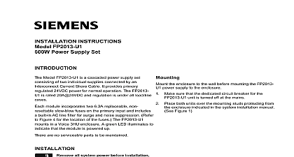
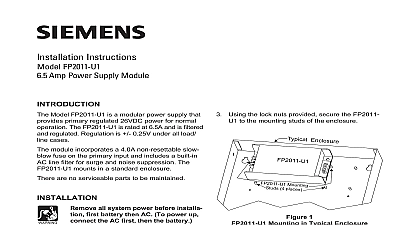
Installation Instructions FP2012 U1 Power Supply Module Model FP2012 U1 is a modular power supply that primary regulated 24VDC power for normal The FP2012 U1 is rated 11.5A 24VDC and is under all load line cases module incorporates two 6.3A replaceable non slow blow fuses on the primary input and a built in AC line filter for surge and noise Refer to Figure 3 for the location of the The FP2012 U1 mounts in a standard enclosure FHB2002 xx FS20 Backbox A green LED illumi to indicate that the module is powered up are no serviceable parts to be maintained all system power before installa first battery then AC To power up the AC first then the battery installation kit for the FP2012 U1 includes the Power Supply Unit lock nuts Instruction Place the FP2012 U1 housing over the four studs in the enclosure indicated in the system manual Refer to Figure 1 for a typical Note that depending on the enclosure it possible to mount the FP2012 U1 in either a or vertical position Using the lock nuts provided secure the FP2012 U1 the mounting studs of the enclosure 240VAC installation reference the Selector Switch on Figure 3 installing the FP2012 U1 module the enclosure to the wall before mounting the power supply to the enclosure Make sure that the dedicated circuit breaker for FP2012 U1 is turned off at the mains Mounting in Typical Enclosure 1 Industry Inc Technologies Division Park NJ Canada Limited Technologies Division Kenview Boulevard Ontario L6T 5E4 Canada FP2012 U1 is designed to operate from a 120 50 60Hz power source Use a separate or circuit breaker Wire in accordance with the having jurisdiction and Article 760 of the NEC 70 latest edition the earth ground from a suitable source to the Check local requirements Conduit is not acceptable earth ground conductor Remove the safety cover from the 3 position block and place it to one side Connect the AC mains to the 3 position terminal on the FP2012 U1 as shown in Figure 2 Hot N Neutral G Earth Ground Replace the safety cover back on the terminal for the AC mains Connect the end of the cable to the terminal block indicated in the system installation manual cable is keyed and will connect in only one FUSES RATINGS Power 120 240VAC 3.0A Max 120VAC Max 240VAC 24VDC Current 11.5A 24VDC and Regulated Temperature Range 0 49OC 32 120OF SELECTOR SWITCH FOR 240VAC all system power before installa first battery then AC To power up the AC first then the battery the AC input is 240VAC you will need to set the red on the side of the FP2012 U1 housing to the or 230 position as shown in Figure 3 H N G AWG MIN WITH PCB BOARD PIN OUTS 24VDC 11.5A GND PSSI ACPB AC Power Brownout Supply Status Indicates Brown 2 the FP2012 U1 SELECTOR SWITCH 3 Selector Switch on FP2012 U1