Siemens FT2007 LED annunciator driver Installation Instruction

File Preview
Click below to download for free
Click below to download for free
File Data
| Name | siemens-ft2007-led-annunciator-driver-installation-instruction-3126947085.pdf |
|---|---|
| Type | |
| Size | 949.38 KB |
| Downloads |
Text Preview
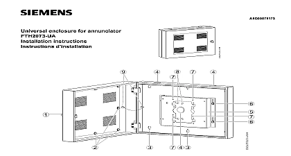
LED annunciator driver Instruction 6 Connection terminal X201 for 17 inputs Dip switch Reserved connection terminal Connection terminal for buzzer EOL jumper Connection terminal X203 X204 for UFP line Connection terminal X301 X501 for 3 x 32 power supply flat cable Connection terminal X202 for 7 LEDs Mounting holes 10 pcs LEDs red LED indicates event yellow LED indicates event yellow LED indicates event For Canadian applications the is deemed supplementary and can be used for display only It must be in a ULC S527 approved locked enclosure Not approved for UL ULC MNS applications Industry Inc Technologies Division use LED annunciator driver FT2007 U1 for the fire detection is connected to the RS485 line It serves for system event signaling and may be installed in an UL certified device complies with Part 15 of the FCC Rules is subject to the following two conditions This device may not cause harmful interference This device must accept any interference received interference that may cause undesired operation contents following are included in the scope of delivery FT2007 U1 Cable ties 3 pcs EOL jumper connecter 1 pcs Buzzer 1 pcs Connection terminals 4 pcs Mounting hardware 10 sets Flat cable clamp with adhesive 2 pcs Cable tie mount 2 pcs instructions of injury to persons and damage to observe the following safety instructions The devices are only intended for stationary installation in rooms The devices may only be connected to the UFP line Static discharge precautions should be taken when the FT2007 U1 housing for the FT2007 U1 LED annunciator driver be provided separately The minimum housing requirement must be UL certified to protection category IP30 and be made of If panel AUX power is not used an UL listed recognized fire use regulated power limited 24V DC power is required by Industry Inc Technology Division Fernwood Road Park NJ 08932 1 973 593 2600 No For mounting the FT2007 U1 directly in a housing or on plate 10 holes of 0.134 inch are provided Mount the FT2007 U1 using 10 screws Connect cables and power supply to connection terminal in with the connection diagram Configure Dip switch 2 and EOL jumper 5 as needed Dip switch is used for setting the FT2007 U1 address baud rate The first 1 4 digits are for setting address the digits are for setting UFP communication baud rate The digits are reserved for future use Rate bps bps On bps Off bps On Off Off Off On Off Off On Off Off Off On Off Off On Off On On Off On On Off Off Off On data W x H x D inch temperature temperature supplied by voltage current current supplied flat cable for switch and LED outputs output voltage lb x 5.984 x 1.232 rel DC Nominal DC mA mA AWG 10 20 and 50 pin density 1.0mm pitch DC positive common When you configure the 7 LEDs the 1st LED be the power LED When you configure the 17 inputs the 17th input be the key switch for button lockout When key switch is not required input at pin 17 be shorted to pin 18 to bypass the lockout Siemens Industry Inc specifications and availability subject to change without notice