Siemens FT2014-xx, FT2015-xx Remote display, Remote terminal

File Preview
Click below to download for free
Click below to download for free
File Data
| Name | siemens-ft2014-xx-ft2015-xx-remote-display-remote-terminal-2301746598.pdf |
|---|---|
| Type | |
| Size | 1.55 MB |
| Downloads |
Text Preview
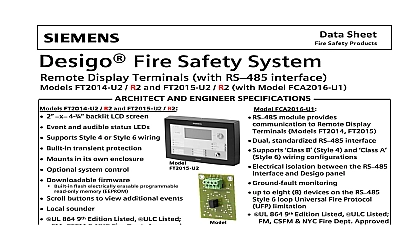
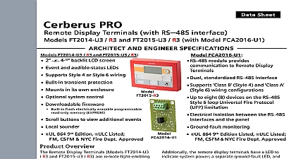
FT2014 xx FT2015 xx display Remote terminal Infrastructure notice notice specifications and availability subject to change without notice reproduction dissemination and or editing of this document as well as of its contents and communication thereof to others without express are prohibited Offenders will be held liable for payment of damages All created by patent grant or registration of a utility model or design patent are by Industry Inc Infrastructure Fernwood Road Park NJ 07932 1 973 593 2600 2019 11 25 ID A6V10315046 g en Siemens Industry Inc 2016 16 of contents display FT2014 remote terminal FT2015 Mounting box of printed circuit board Wiring RS485 circuit connection terminals connection for key switch and ground cable elements data Statement 16 16 display FT2014 remote terminal FT2015 Remote display FT2014 remote terminal 1 Remote display FT2014 left and remote terminal FT2015 right Description and FT2015 are synchronized with of the configured visibility and the same event texts The two devices are connected to the control panel via RS485 circuit remote display and the remote terminal are available in the following versions FT2014 remote display red FT2014 remote display black FT2015 remote terminal red FT2015 remote terminal black features Connection to the RS485 circuit as class or class Power supply from the associated fire control panel or fire voice control panel External supply possible 8 line display each with 40 characters per line and backlight Buzzer Operation enabled by key switch Indication of alarms and troubles Bypass for installed buzzer Three LEDs configurable with the engineering tool set Inscription strips for sliding in features of the remote terminal FT2015 Acknowledgement and resetting of alarms and troubles Three buttons configurable with the engineering tool set 16 display FT2014 remote terminal FT2015 references templates for the inscription strips and the operating instructions with button and designations have the following document IDs strips UL strips ULC A6V10396857 PRO strips UL strips ULC A6V10396859 Mounting is identical for FT2014 and FT2015 2 Mounting view taking example of FT2015 fixing screw on the top part of the housing box slot for cable tie threaded hole for fixing screws fixing slot for wall mounting 16 display FT2014 remote terminal FT2015 entry holder cam for housing Loosen the fixing screws on the top part of the housing and remove the from the back box by tilting it forward and pulling it down Position the back box such that the cables can be led correctly through the cable Mark the fixing slots in this position Drill the holes and secure the back box to the wall by inserting dowel screws the fixing slots Wire up the device according to the wiring diagram Fix the cables to the slots with cable ties and mount the housing on the back by following step 1 in reverse also Wiring 9 back box 7 Views back box drawing for the back box 3 Dimensions of the back box of the FT2014 and FT2015 view from inside 16 1firealarmresources com display FT2014 remote terminal FT2015 1 Dimensions of the fixing slots 4 Detailed view of the fixing slots table 16 display FT2014 remote terminal FT2015 View of printed circuit board 5 Printed circuit board view of remote display and remote terminal for ribbon cable to display for ribbon cable to display plug for supply and circuit output plug for input supply and line input for key switch switch 8 pole for address setting and other functions key indicators front Wiring circuit must not be terminated on the side of the RS485 class A module because RS485 class A module has integrated terminating resistors wiring as a class circuit the circuit on the last device must be terminated with 120 resistor 16 display FT2014 remote terminal FT2015 from the remote display and remote terminal to the RS485 circuit a class B 6 FT2014 FT2015 class wiring from the remote display and remote terminal to the RS485 circuit a class A 7 FT2014 FT2015 class wiring X5 X6 RS485 circuit connection terminals X6 NET IN supply input DC supply input DC port of RS485 circuit input port of RS485 circuit input 16 class A module iso FirstFT2014 FT2015Fire system panel24 V AUX Terminate circuitwith 120 resistor AFBFARBR1234 AB1234 ABNET INX6NET OUTX51234 AB1234 ABNET INX6NET OUTX5LastFT2014 FT2015FCA201634X221RS485 class A module iso FirstFT2014 FT2015Fire system panel24 V AUX AFBFARBR1234 AB1234 ABX5X6NET INNET OUT1234 AB1234 ABX5X6NET INNET OUTLastFT2014 FT2015FCA2016firealarmresources com display FT2014 remote terminal FT2015 X5 NET OUT supply output DC to cascade supply output DC to cascade port of RS485 circuit output to cascade port of RS485 circuit output to cascade X11 connection for key switch and ground cable 8 Wiring of the key switch and ground cable switch T45 connection on back box cable pre configured l washer with plug connection connections for cable lug for key switch pre configured l 16 display FT2014 remote terminal FT2015 elements Connection for key switch connection cable Connect the pre configured ground cable 3 by inserting the flat connector into the connection of the grounding washer 4 Using a washer and nut screw the cable lug at the other end of the ground cable onto the threaded bolt in the back box 2 so that it is secure Tighten both cable lugs of the key switch cable 6 at the contacts 5 of the key Plug the other end of the key switch cable 6 into connector X11 on the printed 1 board Adjustment elements key S2 reset key S2 has two functi