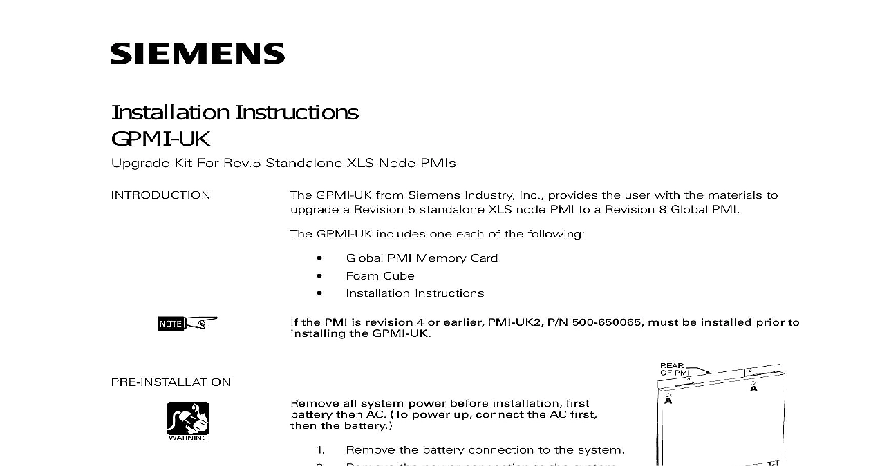
Siemens GPMI-UK Upgrade Kit For Rev 5 Standalone XLS Node PMIs, Installation Instructions
File Preview
Click below to download for free
Click below to download for free
File Data
| Name | siemens-gpmi-uk-upgrade-kit-for-rev-5-standalone-xls-node-pmis-installation-instructions-3164057928.pdf |
|---|---|
| Type | |
| Size | 836.72 KB |
| Downloads |
Text Preview
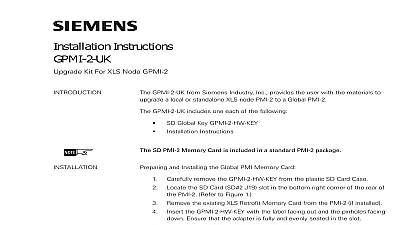
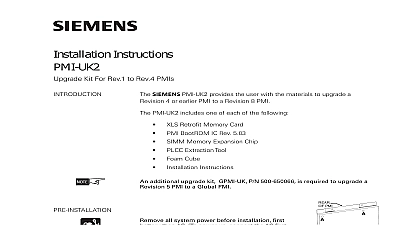
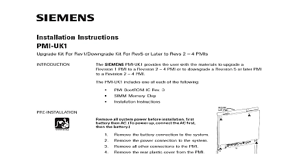
Installation Instructions Kit For Rev 5 Standalone XLS Node PMIs GPMI UK from Siemens Industry Inc provides the user with the materials to a Revision 5 standalone XLS node PMI to a Revision 8 Global PMI GPMI UK includes one each of the following PMI Memory Card Cube Instructions the PMI is revision 4 or earlier PMI UK2 P N 500 650065 must be installed prior to the GPMI UK all system power before installation first then AC To power up connect the AC first the battery the battery connection to the system the power connection to the system all other connections to the PMI the rear plastic cover from the PMI is held in place by four mounting screws The of the screws is marked A in 1 Place the screws to one side PMI 1 Of PMI remove the memory card from the anti static bag the Global PMI Memory Card into the PCMCIA slot of of your Zeus Log on to Zeus 8.00.0023 Then using the To PCMCIA option transfer the following files the memory card Refer to Figure 2 complete do NOT log off Zeus as the configuration will be used again in a step and Installing the Global PMI Memory Card 315 050066 2 Inc Inc Inc Industry Inc Inc TTTTTececececechnologies Di Di Di Division Di 2 5.0 Transfer Menu the PCMCIA slot P4 in the upper right corner of the rear of the Refer to Figure 3 the existing XLS Retrofit Memory Card from the PMI if installed the Global PMI Memory Card with the label facing out and the facing down Ensure that the adapter is fully and evenly seated in slot Do not bend the slot forward during insertion the old XLS Retrofit Memory Card if previously installed until completion of the system upgrade OF PMI 3 Of PCMCIA Card Industry Inc Technologies Division 315 050066 2 the PCMCIA Positioning Foam if not previously installed the protective covering from the adhesive side of the foam cube the foam on the inside of the PMI rear cover as shown in Figure 4 the foam firmly into place the rear plastic cover and secure with the four mounting screws CUBE 4 The PCMCIA Positioning Foam and Configuring the PMI power battery to the PMI in the firmware upgrade mode To enter mode place DIP switch 2 on the options DIP switch located at the edge of the PMI in the ON position Refer to Figure 5 the RESET button on the rear of the PMI a short delay the Status display will begin to show the version of the ROM First a small will appear followed by the Boot ROM version e g r5.01.0004 Once this has begun the PMI firmware can be via Zeus the programming cable to the UPLOAD port and install the As the firmware is being installed the Status display will show an which turns on and off at a slow rate Using the Zeus configuration tool select To Panel transfer the PCMCIALoader bin file Version 05.01.0004 to the PMI Once completed the Status display will show Then use Zeus to transfer desired MR5 configuration to the panel via the To Panel option is displayed return DIP switch 2 to the OFF position the RESET button on the rear of the PMI The PMI will now restart the upgraded firmware Industry Inc Technologies Division 315 050066 2 0 0 0 DEBUG 9 5 Options DIP Switch On PMI Industry Inc Technologies Division Park NJ Canada Limited Technologies Division Kenview Boulevard Ontario L6T 5E4 Canada 315 050066 2