Siemens HCP-Z Intelligent Control Point, Installation Instructions

File Preview
Click below to download for free
Click below to download for free
File Data
| Name | siemens-hcp-z-intelligent-control-point-installation-instructions-8052917436.pdf |
|---|---|
| Type | |
| Size | 844.98 KB |
| Downloads |
Text Preview
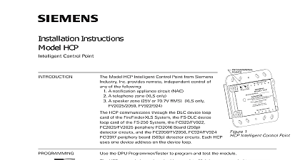
Installation Instructions HCP Z Control Point the DPU Programmer Tester to program and test the module Model HCP Z Intelligent Control Point from Siemens Inc provides remote independent control of of the following A notification appliance circuit NAC A telephone zone XLS only A speaker zone 25V or 70.7V RMS XLS only FV922 924 HCP Z communicates through the DLC device loop of the FireFinder XLS System the FS DLC device card of the FS 250 System the FC922 FV922 periphery FCI2016 Board 250p circuits and the FC2050 FV2050 FC924 FV924 periphery board 500p detector circuits Each uses one device address on the device loop B 1 O N B A C K S I D E I E M E N S O D E L H C P Z E V I C E A D D R E S S A U T I O N I S C O N N E C T W I R E A T T E R M I N A L 1 2 N T B 1 B E F O R E P R O G R A M M I N G N S TA L L A T I O N I N S T R U C T I O N S N 3 1 5 0 3 4 8 6 0 I E M E N S I N D U S T R Y L O R H A M P A R K N J 0 7 9 3 2 N C B 2 O N B A C K S I D E 1 Intelligent Point HCP Z may only be assigned addresses 1 to 60 It is recommended to program HCP Z devices first to ensure that enough addresses have been reserved for Other devices may then be assigned to addresses in this range that were not to an HCP Z wire at terminal 1 and 2 on TB1 before programming set the HCP Z device address the programming cable of the DPU Programmer Tester into the two programming points on the HCP Z See Figure 1 for location the device address for the HCP Z by following the instructions in the Programmer Tester Manual P N 315 033260 HCP Z can be assigned a custom message using either the Zeus Programming XLS System the FS CT2 FS 250 System the FC2025 2050 FV2025 2050 Engineering Tool or the FC922 924 FV922 924 FSX7212 Engineering Tool to the Zeus Quick Start Manual P N 315 033875 or the FS 250 Programming P N 315 049403 as applicable Industry Inc Industry Industry Inc Inc Industry Inc Industry Inc TTTTTececececechnologies Di Di Di Division Di following minimum revisions are required for proper operation of the HCP Z Loops all system power before installation first battery then AC To power up the AC first then the battery down the 24 VDC power supply and the input source ZAC etc before the HCP Z wiring must comply with national and local codes All wire must be 18 AWG 12 AWG maximum HCP Z communicates with the FireFinder XLS FS 250 Desigo FC2025 2050 PRO FC922 924 FV922 924 Systems through its addressable loops These loops are connected to the DLC via terminal blocks on the CC 5 CC 2 cardcage XLS or to the FS DLC via TB3 on the FS MB FS MB2 main board They may be wired Class A Style 6 or Class B Style 4 Figure 2 shows wiring types and the connections to the DLC See the DLC Installation Instruc P N 315 033090 for more information Figure 3 shows both wiring types and to the FS DLC See the FS 250 Installation Operation and Maintenance P N 315 049353 for more information Figure 4 shows both wiring types and to the Periphery boards See the Desigo FC2025 2050 FV2025 2050 Manual Document ID A6V10315023 for more information Figure 5 both wiring types and connections to the Periphery boards See the Cerberus FC922 924 FV922 924 Configuration Manual Document ID A6V10333423 for information Power Supply FireFinder XLS Systems compatible power supplies for the HCP Z are the PSC PSX 12 and PAD 4 Wiring should be connected to TB3 on the PSC 12 and PSX 12 the auxiliary power supply on the PAD 4 FS 250 Systems the HCP Z is powered by the NAC circuits and PAD 4 Wiring be connected to the NAC circuits on the main board or the auxiliary power on the PAD 4 Industry Inc Technologies Division Loop resistance 50 ohms with 252 devices on loop Refer to the DLC Instructions 315 033090 if the of devices is less 252 12 18 AWG wire No EOL device required Supervised power limited NEC 760 All wiring must conform national and local codes A WIRING B WIRING IN FULL CONFORMANCE WITH STYLE 6 ULC DCLA IN FULL CONFORMANCE WITH STYLE 4 ULC DCLB T TAPPING ALLOWED ZONES MUST BE WIRED AS CLASS A ALLOWED ZONES MUST BE WIRED AS CLASS B 1 2 1 2 2 Device Loop LOCATED IN SLOT OF CC 5 CC 2 LOCATED IN SLOT OF CC 5 CC 2 A WIRING B WIRING circuits on periphery board FC922 FV922 FC2025 FV2025 Loop resistance 180 ohms with 252 devices on 12 18 AWG wire No EOL device required Supervised power limited NEC 760 All wiring must conform national and local codes 3 Device Loop Industry Inc Technologies Division Loop resistance 50 ohms with 252 devices on loop Refer to the FS Manual P N 315 if the number of is less than 252 12 18 AWG wire No EOL device required Supervised power limited NEC 760 All wiring must conform national and local codes 4 Device Connections Loop Test As NAC Module Device Circuit A INSTALLATION T TAPPING ALLOWED IN FULL CONFORMANCE WITH STYLE 6 ULC DCLA Device Circuit B INSTALLATION ALLOWED IN FULL CONFORMANCE WITH STYLE 4 ULC DCLB 1 OUT 1 RETURN 2 RETURN 2 OUT 1 USED USED 2 performing a loop test with the DPU be sure to apply power to the HCP Z power applied to the HCP Z a blinking will appear on the DPU indicating the HCP Z is in trouble application uses the principle of polarity reversal to activate notification appli Wiring is shown in Figure 4 Connect the HCP Z output zone wiring to the terminals of each notification appliance as shown in Figure 4 For a list of devices refer to P N 315 096363 used as a NAC module the 24VDC provides power for the supervision circuitry to the notification appliances when they are activated The power source must be limited See the HCP Z Power Supply section above for compatible power The maximum output load that may be connected to an H