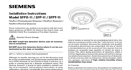
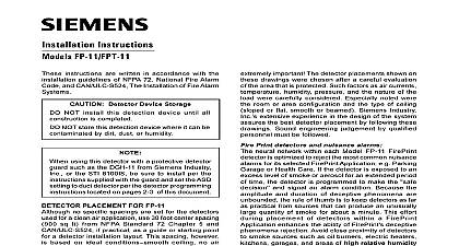
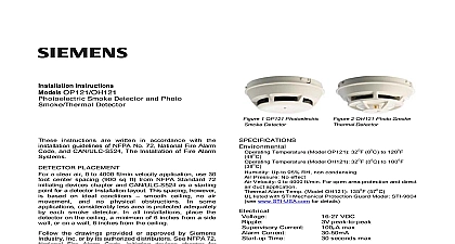
Siemens HFP-11 HFPT-11 FirePrint Detector FirePrint Thermal Detector, Installation Instructions

File Preview
Click below to download for free
Click below to download for free
File Data
| Name | siemens-hfp-11-hfpt-11-fireprint-detector-fireprint-thermal-detector-installation-instructions-4763085129.pdf |
|---|---|
| Type | |
| Size | 669.66 KB |
| Downloads |
Text Preview
Installation Instructions HFP 11 HFPT 11 Detector FirePrint Thermal Detector instructions are written in accordance with the installa guidelines of NFPA 72 National Fire Alarm Code and The Installation of Fire Alarm Systems Device Storage NOT install this detection device until all construc is completed NOT store this detection device where it can be con by dirt dust or humidity using this detector with a protective guard such as the DGH 11 from Siemens Indus Inc or the STI 8100IS be sure to install per the in supplied with the guard and set the ASD set to duct detector per the detector programming in located on page 2 of this document DETECTOR PLACEMENT no specific spacings are set for the detectors used a clean air application use 30 foot center spacing 900 sq from NFPA Standard 72 and CAN ULC S524 if practical as guide or starting point for a detector installation layout This however is based on ideal conditions ceil no air movement and no physical obstructions In some therefore considerably less area is protected ad by each smoke detector This is why it is mandatory closely follow the installation drawings In all installations the detector on the ceiling a minimum of 6 inches from side wall or on a wall 4 to 6 inches from the ceiling you have any questions regarding detector placement fol the drawings provided or approved by Siemens Industry or by its authorized distributors This is extremely impor The detector placements shown on these drawings were after a careful evaluation of the area that is protected factors as air currents temperature humidity pressure the nature of the fire load were carefully considered Es noted were the room or area configuration and the of ceiling sloped or flat smooth or beamed Siemens Inc extensive experience in the design of the sys assures the best detector placement by following these Sound engineering judgment by qualified person must be followed 315 033290 11 1 and HFPT 11 Print Detectors And Nuisance Alarms neural network within each Model HFP 11 FirePrint detector optimized to reject the most common nuisance alarms for its FirePrint Application e g Parking Garage or Health Care the detector is exposed to an excess level of smoke or aerosol an extended period of time the detector is programmed to the decision and signal an alarm condition Because amplitude and duration of deceptive phenomena are un the rule of thumb is to keep detectors as far as practi from sources that can produce an unusually large quantity of for about a minute This effort during placement of detec within a FirePrint Application enhances the ability of FirePrint phenomena rejection Avoid close proximity of detec to smoke sources such as oil burners electric heaters kitch garages and areas of high relative humidity where con may occur Currents a detector can sense a fire the products of combustion smoke must travel from the fire to the detector This travel especially influenced by air currents therefore consider air when designing the system While combustion tend to rise drafts from hallways air diffusers fans may help or hinder the travel of combustion products to detector When positioning a detector at a particular loca give consideration to windows and doors both open and to ventilating systems both in and out of operation to other factors influencing air movement Do not install a in the air stream of a room air supply diffuser It is to position a detector closer to an air return distance that products of combustion or smoke travel a fire to the detector is not usually the shortest linear Combustion products or smoke usually rise to the ceil then spread out Average ceiling heights of 8 to 10 feet not abnormally affect detector response High ceilings lo in churches warehouses auditoriums etc do affect response and should be considered Ceiling Construction Factors obstructions change the natural movement of air and products Depending on the direction of smoke joists and beams can slow the movement of heated air smoke while pockets between them can contain a re level of smoke Take obstructions created by girders beams air conditioning ducts or architectural design consideration when determining area protection Refer the Initiating Devices chapter of NFPA Standard 72 for Lo and Spacing requirements for specific types of con e g beam suspended level sloped and peaked Inc Inc Inc Industry Inc Inc TTTTTececececechnologies Di Di Di Division Di DETECTOR PLACEMENT Model HFPT 11 on the ceiling at least 4 inches from side walls For an ideal smooth ceiling condition place detectors at a maximum center spacing of 50 feet 2500 feet Locate detectors 25 feet from side walls or room For FM Approved installations this device has an rating of FAST Use maximum center spacing of 25 feet square feet Locate detectors 12.5 feet from side walls room partitions job conditions and sound engineering judgment must detector spacing Consider environmental factors ambient temperature fluctuation and the nature of fire hazard Room or area configuration and ceiling type or flat smooth or beamed also dictates placement questions arise regarding detector placement follow drawings provided and or approved by Siemens Industry or by its authorized distributors This is extremely impor The detector placements shown on these drawings were after a careful evaluation of the area being protected Industry Inc extensive experience in design of the assures the best detector placement by following drawings Humidity Pressure Air Velocity operating temperature range for the HFP 11 and HFPT 11 is 32 0 to 100 38 The thermal alarm is rate compensated at 135 57 these in environments where the humidity does not ex 93 non condensing Normal changes of atmospheric do not affect detector sensitivity For HFP 11 open 0 1200 ft min applications use the appropriate applica from the FirePrint ASD application list Use the ASD duct for 300 4000 ft min applications a in above ceil and under floor plenums b inside an air duct and c in an duct housing using sampling tubes Follow detector spac and location requirements in NFPA 72 Chapter 5 for High Movement Areas and Control of Smoke Spread installing Model HFP 11 in existing installations with an duct detector housing order an AD 11UK Air Duct Kit DA 304 P N 500 695967 and use it in that installation kit includes the required housing cover P N 305 095676 not use Model HFP 11 with any other air duct cover air duct and open area applications the smoke sensitivity range is indicated on its name For application sensitivity settings refer to the System Manual P N 315 033744 or the Manual P N 315 049353 Indicators Model HFP 11 HFPT 11 contains an LED indicator ca of flashing either one of three distinct colors green or red During each flash interval the microprocessor detector checks the following smoke in its sensing chamber its smoke sensitivity is within the range indicated the nameplate label its critical smoke sensing electronics are on the results of these checks the LED indicator flashes following PROGRAMMING detector on a loop must be programmed to respond to unique system address between 001 252 program the detector address use the Model DPU Programming Unit Refer to the DPU Manual 315 033260 the loop and device number system address the detector on the detector label and on the base to installing the detector in the wrong base The DPU label printer can be used for this purpose Guard Programming using the DGH 11 or the STI 8100IS detector gua