Siemens HI121 Thermal Detector, Installation Instructions

File Preview
Click below to download for free
Click below to download for free
File Data
| Name | siemens-hi121-thermal-detector-installation-instructions-0129785463.pdf |
|---|---|
| Type | |
| Size | 676.89 KB |
| Downloads |
Text Preview
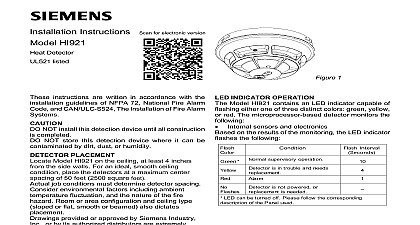
Installation Instructions HI121 Thermal Detector instructions are written in accordance with the guidelines of NFPA 72 National Fire Alarm Code CAN ULC S524 The Installation of Fire Alarm Systems Device Storage NOT install this detection device until all is completed NOT store this detection device where it can be by dirt dust or humidity PLACEMENT the HI121 on the ceiling at least 4 inches from the walls For an ideal smooth ceiling condition place the at a maximum center spacing of 50 feet 2500 feet 25 feet from side walls or room partitions For Approved installations this detector has an RTI rating QUICK which allows a maximum center spacing of 20 400 square feet Locate detectors 10 feet from side or room partitions job conditions and sound engineering judgment be used to determine detector spacing Consider factors including ambient temperature and the nature of the fire hazard Room or area and ceiling type sloped or flat smooth or also dictates placement questions arise regarding detector placement follow drawings provided and or approved by Siemens Industry or by its authorized distributors This is extremely 1 HI121 Thermal Detector The detector placements shown on these were chosen after a careful evaluation of the area protected Siemens Industry Inc s extensive in design of the system assures the best detector by following these drawings Temperature 32OF 0OC to 100OF 38OC Up to 95 RH non condensing Pressure No effect Temp 135OF 57OC Current Current Time VDC peak to peak max seconds max WIRING HI121 should be connected as shown in Figure 2 using separate mounting base Model DB 11 Follow the panel wiring connection drawing installed on the face of each control panel cover See DB 11 P N 315 094193 for base mounting Duplicate information is also in the Installation Operation and Manual provided with every control panel any limitations on the number of detectors and on the use of remote devices permitted for circuit CONNECT DETECTOR ONLY TO CIRCUITS SPECIFIED IN DETECTOR PANEL LITERATURE OR SYSTEM MAY NOT OPERATE REMOTE DEVICE REMOTE DEVICE S INITIATING OF INC PANEL CAUTION 1 REMOTE DEVICE INSTRUCTIONS WIRING DETAILS RLW 11 RSAW 11 315 094924 315 094925 315 094926 315 096162 Do not use looped wire under base terminal 5 wire run to provide supervision of When a remote relay is used to control a critical function the relay and its associated and optional module s must be the devices on the initiating circuit REMOTE DEVICES remote devices are supported by the initiating circuit detector base may have up to 2 remote devices the following configurations and restrictions only 1 RLW 11 RLW 11 2 RLW 11 RSAW 11 RSAW 11 RLW 11 Caution 2 Caution 2 from base to RL 11 OF 2 Installation and Wiring Diagram for HI121 Conventional Detector Inc Inc Inc Industry Inc Inc TTTTTececececechnologies Di Di Di Division Di INSTALL Rotate detector counterclockwise while gently pressing REMOVAL OF DETECTOR it until the detector drops fully into base Then rotate the detector clockwise until it stops and in place Insert optional locking screw Order LK 11 REMOVE locking screw if installed Then rotate the detector until stop is reached Pull detector out base INDICATOR OPERATION HI121 contains an LED indicator capable of flashing one of three distinct colors green yellow or red microprocessor based detector checks that its critical are operating on the results of these checks the LED indicator as follows AND MAINTENANCE requires no test equipment A green flash of the LED about every 10 seconds indicates that the is operating properly The minimum test schedule be found in the current edition of NFPA 72 inspection and maintenance chapter for installations in the U S CAN ULC S537 The Verification of Fire Alarm for installations in Canada 3 HI121 with Magnet 4 TM121 Test Placement and control panel functionality can also be tested the TM121 test magnet as shown in Figure 3 Place magnet in the specific area at the bottom of the detector is shown in Figure 4 for at least 5 seconds with the side towards the centered LED The detector will an alarm to the panel Testing with the magnet only tests the circuit does not test the detector sensing ability The TM121 test magnet is a strong magnet can be harmful to pacemaker wearers and to those medical implants Keep the magnet away from media such as credit cards and memory disks UNDER NO CIRCUMSTANCES IS THE HEAD TO BE DISASSEMBLED NO REPAIRS BE ATTEMPTED NOT PAINT detector base plastic is marked DO NOT PAINT This intended to prohibit painting during routine maintenance the occupancy which can affect proper operation of the Industry Inc Technologies Division Park NJ Canada Limited Technologies Division Kenview Boulevard Ontario L6T 5E4 Canada