Siemens HMS-M Manual Pull Station with Metal Housing, Installation Instructions

File Preview
Click below to download for free
Click below to download for free
File Data
| Name | siemens-hms-m-manual-pull-station-with-metal-housing-installation-instructions-7698520143.pdf |
|---|---|
| Type | |
| Size | 663.06 KB |
| Downloads |
Text Preview
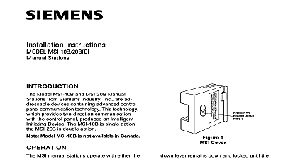
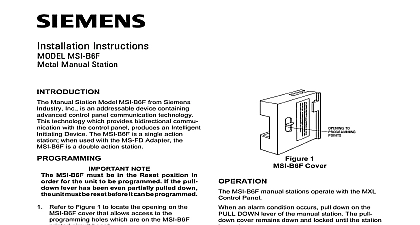
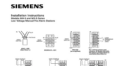
Installation Instructions HMS M Pull Station with Metal Housing to Figure 1 to locate the opening on the HMS cover that allows access to the holes which are on the HMS printed circuit board Manual Station Model HMS M from Siemens Inc is a field installed addressable device advanced control panel communication This technology which provides two communication with the control panel an Intelligent Initiating Device The HMS M is single action station when used with the MS FD the HMS M is a double action station TO 1 Cover HMS M must be in the Reset position in order for the unit to be programmed If PULL DOWN lever has been even partially pulled down the unit must be reset it can be programmed manual station is programmed by using the DPU Programmer Tester Because devices are polarity insensitive the programming plug can be inserted into the holes in either direction prevent potential damage to the DPU DO NOT connect an HMS to the DPU until least one wire is removed from terminals 1 or 2 of the HMS the instructions in the DPU Manual P N 315 033260 to connect the cable and program the HMS to the desired address Record the device address the nameplate label located on the inside of the HMS M manual station mounting The HMS can now be installed and wired to the system HMS M manual station operates with the FireFinder XLS or FS 250 Control via the DLC or FS DLC Device Loop Card an alarm condition occurs pull down on the PULL DOWN lever of the manual The pull down cover remains down and locked until the station is reset HMS M with the MS FD Adapter has an additional lever labeled LIFT PULL which must be lifted up before access is provided to the station PULL lever 315 033450 6 Industry Inc Technologies Division 1 2 1 2 STYLE 4 6 TO DLC INSTALLATION P N 315 033090 NEXT ADDRESSABLE DEVICE INITIATING CONTROL PANEL PREVIOUS ADDRESSABLE DEVICE GROUND 2 Information Recommended wire sizes AWG minimum 14 AWG maximum Wire larger than 14 AWG can damage the connector When using shielded cable without metal raceway or with raceway the shields should be terminated at the device terminal If the device box is already grounded by another such as being mounted to a grounded structure the wire should be continuous and must be grounded solely at the point origin for example at the control panel When using shielded cable with metal raceway the wiring shields be continuous and grounded solely at the point of origin The ground terminal shall be connected to the grounded device box When using metal raceway without shielded cable connect the ground terminal to the grounded device box Metal raceway should be thoroughly grounded throughout the system The HMS M is a polarity insensitive device Line 1 and Line 2 can be supervisory HMS M draws 1mA line of the DLC or FS DLC loop the manual station boxes throughout the protected area so that they unobstructed readily accessible and located in the normal exit path Place the station according to the regulations of the authorities having jurisdiction Mounting the backplate to a Model MS FB Backbox as shown in Figure 3 Mounting the backplate to a user supplied single gang switchbox as shown in Figure 3 not overtighten the screws Overtightening may distort the backplate Reset Station lock barrel turn counter clockwise with the allen key provided This will allow front to hinge down releasing PULL DOWN plate to disengage from the switch the front to its closed position then turn the lock barrel back clockwise MS FB MS FD ACTION ADAPTER SEPARATELY in INCH DEEP BOX SUPPLIED in HMS M STATION 3 The HMS M RATINGS Industry Inc Technologies Division Park NJ Building Technologies Ltd Safety Security Products Kenview Boulevard Ontario L6T 5E4 Canada 315 033450 6