Siemens HTRI-MZ Addressable Interface Module, Installation Instructions

File Preview
Click below to download for free
Click below to download for free
File Data
| Name | siemens-htri-mz-addressable-interface-module-installation-instructions-6372809145.pdf |
|---|---|
| Type | |
| Size | 690.88 KB |
| Downloads |
Text Preview
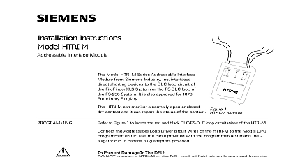
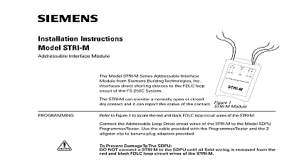
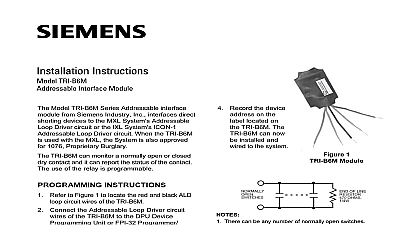
Installation Instructions HTRI MZ Interface Module to Figure 1 to locate the red and black DLC FS DLC loop circuit wires of the HTRI Model HTRI MZ Series Addressable Interface from Siemens Industry Inc interfaces shorting devices to the DLC loop circuit of FireFinder XLS System or the FS DLC loop of FS 250 System It is also approved for 1076 Burglary HTRI MZ can monitor a normally open or dry contact and it can report the status of the contact LINE POWER LIMITED 1 Module the Addressable Loop Driver circuit wires of the HTRI MZ to the Model DPU Use the cable provided with the Programmer Tester and the 2 clip to banana plug adapters provided Prevent Damage To The DPU NOT connect a HTRI MZ to the DPU until all field wiring is removed from the and black DLC FS DLC loop circuit wires of the HTRI MZ from the DPU to the HTRI MZ is not polarity sensitive Refer to 3 for the proper connections to the control panel to Figure 2 Follow the instructions in the DPU Programmer Tester Manual 315 033260 to program the desired address into HTRI MZ the device address on the label located on the HTRI MZ The HTRI MZ can be installed and wired to the system CLOSED NOTE 4 OPEN NOTES 2 3 AND 5 OF LINE OHMS OF LINE OHMS There can be any number of normally closed or normally open switches The end of line resistor must be located at the last switch Do not wire a normally closed switch across the end of line resistor Only for use with security and status applications Do not use N O switches for security applications 2 Switches Inc Inc Inc Industry Inc Inc TTTTTececececechnologies Di Di Di Division Di to Figure 3 Refer to the wiring diagram and wire the addressable interface accordingly wire size AWG minimum AWG maximum SWITCH NOTES 1 AND 2 OHM OF LINE DEVICE NOTE 2 NOTE 5 2 1 2 1 FIREFINDER XLS FS 250 PANEL ADDRESSABLE DRIVER CIRCUIT OR FROM ADDRESSABLE DEVICE NEXT DEVICE 3 the HTRI MZ Wiring All supervised switches must be held closed and or open for at least a quarter of a second to guarantee detection End of line device 470 ohm 1 4W resistor P N 140 820164 For Canadian applications use Model EL 33 with 470 ohm 1 4W resistor HTRI MZ is polarity insensitive Line 1 and Line 2 can be either line of the loop The supervised switches have the following ratings maximum VDC maximum during polling resistance maximum 10 ohms cable length feet 18 AWG to line 0.02uF line size 14 AWG to shield 0.04uF line size 18 AWG shield ONLY at the specified location on the Control Panel device must be a 470 ohm 1 4 W resistor replacing an existing HTRI on a device loop must also replace the EOL resistor if it is not ohms 1 4W The green wire must be connected to earth ground Use wire nuts to pass the shield wire through the electrical box with NO connection to the device green wire Use shielded wire to connect the switch wiring Tie the switch wiring shield to earth ground For proprietary burglary application Use a TSW 1 2 tamper switch to monitor the main enclosure Monitor each HTRI MZ related to this application continuously by using a listed motion detector to prevent tampering supervisory HTRI MZ draws 1.3mA All circuits are power limited Positive and negative ground fault detected at 25K ohms for orange terminals Model HTRI MZ mounts directly into a single gang switchbox supplied the appropriate wires using wire the HTRI MZ module inside the box and dress the wiring as See Figure 4 4 the HTRI MZ FS DLC Loop Current NOT REAR SUPPLIED SINGLEGANG SUPPLIED RATINGS Industry Inc Technologies Division security disclaimer products and solutions provide security functions to ensure the secure operation of comfort fire safety security management and physical security systems The security on these products and solutions are important components of a comprehensive security is however necessary to implement and maintain a comprehensive state of the art security that is customized to individual security needs Such a security concept may result in site specific preventive action to ensure that the building comfort fire safety security or physical security system for your site are operated in a secure manner These may include but are not limited to separating networks physically protecting system user awareness programs defense in depth etc additional information on building technology security and our offerings contact your Siemens or project department We strongly recommend customers to follow our security advisories provide information on the latest security threats patches and other mitigation measures http www siemens com cert en cert security advisories htm Industry Inc Technologies Division PAGE HAS BEEN LEFT INTENTIONALLY BLANK Industry Inc Technologies Division Park NJ Canada Ltd North Service Road East Ontario 0H6 Canada ID A6V11208378 en a A5Q00072528