Siemens ICP-B6 Intelligent Control Point, Installation Instructions

File Preview
Click below to download for free
Click below to download for free
File Data
| Name | siemens-icp-b6-intelligent-control-point-installation-instructions-9624137850.pdf |
|---|---|
| Type | |
| Size | 955.52 KB |
| Downloads |
Text Preview
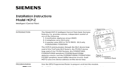
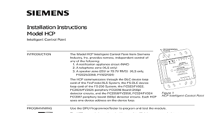
Installation Instructions ICP B6 Control Point Model ICP B6 Intelligent Control Point from Industry Inc can be used as an remotely located telephone zone a zone 25V or 70.7V RMS or notification circuit NAC depending on how it is It communicates through the analog of the MXL MXLV System to 12 ICP B6s can connect to each analog of the MXL MXLV These modules must connected to the first 12 address locations the analog loop 24 VDC power input for each ICP B6 from either the MMB the PSR or from auxiliary power supply which is power and UL listed for fire protective signal use and is rated between 24 and 27.3 Each ICP B6 can be assigned a 32 custom alphanumeric message module uses one address on either the loop of the ALD 2I module or the analog of the MMB board See Figure 1 The is programmable for different usages additional information on the MXL MXLV refer to the MXL MXLVManual P N and Testing the DPU Device Programming Unit or the Programmer Tester SensorLINK to and test the module With FPI 32 Rev 1.3 software only 1 MXL mode should be used when programming a device Set the ICP B6 Module Address 1 Plug the programming cable of the DPU or Programmer Tester SensorLINK the two pin receptacle on the ICP B6 Figure 2 for location only Set the system address for the ICP B6 by the instructions in the FPI 32 Programmer Tester Manual 315 090077 or the DPU User s P N 315 033260 as applicable all system power before installa first battery and then AC To power connect the AC first then the battery wiring must comply with and local codes ICP B6 should be installed in a UL electrical box See Figure 10 Loop ICP B6 communicates with the MXL its analog addressable loops These are on either the MMB or on the op ALD 2I module of the MOM 4 They be wired for Class A Style 6 or Class B 4 Figure 1 shows both wiring types the connections to either the MMB or to MOM 4 when the ALD 2I module is used table on the following page lists the output currents allowed Industry Inc Technologies Division Park NJ 315 095306 10 Building Technologies Ltd Safety Security Products Kenview Boulevard Ontario 5E4 Canada ICP B6 module can be used in four ways Using the ICP B6 as an NAC Module notification appliance application uses the of polarity reversal when there is an Figure 2 shows the polarity connection a supervisory condition When using the as a supervised NAC output module notification appliance devices cut jumper Refer to Figure 2 for additional connec and jumper information and to P N 315 for a list of compatible devices used as an NAC module the output is power limited The ICP B6 maximum is 1.5A at 24 VDC If the 24 VDC is or the NAC line is broken or shorted the condition INPUT DEVICE RESPONSE LOW displays at the MXL MXLV control Refer to Figures 3 and 4 for the con used with the TRI 60 B6 module and PSR 1 module respectively See the Line chart for the allowable line for each ICP B6 output circuit ALLOWABLE ICP B6 OUTPUT CIRCUIT LINE RESISTANCE SPECIFIED DC RISER CURRENT AND LINE RESISTANCE RISER Amps RISER RESISTANCE in Ohms Ohm Ohm Ohm Ohm Ohm Ohms LOOP RESISTANCE FOR EACH ICP B6 ON RISER Resistances specified are for both wires higher currents are required Siemens Industry Inc recommends using a local auxiliary which is UL listed for fire protection signaling use The supply should be rated between and 27.3 VDC RATINGS 1 2 1 2 1 2 RESISTANCE 100 OHMS MAX AWG MINIMUM WIRE EOL DEVICE REQUIRED POWER LIMITED PER NEC 760 WIRING MUST CONFORM TO NATIONAL AND ELECTRICAL CODES LOOP CONNECTION IN FULL CONFORMANCE WITH STYLE 4 CLASS B ALLOWED OHMS MAX CAN BE REMOVED FROM MMB 3 WITH CSGM CONFIGURATION 1 Loop Connections Y STROBE ACTIVATION SPECIAL APPLICATION 9VDC 5mA 16 32V UNFILTERED FULL WAVE RECTIFIED 1.5A MAX SHOWN IN SUPV CONDITION Z 1 2W 5 EOL RESISTOR 140 820400 INPUT RATED 27.3 VDC FWR 1.5A MAX 1 2W 5 RESISTOR 140 820400 VDC UNITS TABLE 1 INPUT SUPPLY PS 35 PSR 1 OR LISTED POWER SUPPLY BY Model BN4 002 UL MODULE IS USED FOR SUPERVISION AND ACTIVATION MODULE IS USED FOR SUPERVISION AND ACTIVATION DC SUPPLY OUTPUT VDC 18mA MAX VDC 0.5mA APPLICATION UNFILTERED FULL WAVE RECTIFIED POWER LIMITED ALL WIRING MUST COMPLY WITH NATIONAL AND LOCAL CODES POSITIVE AND NEGATIVE GROUND FAULT DETECTED AT 5K OHMS FOR TERMINALS 3 6 FOR SYNCHRONIZATION OF NOTIFICATION APPLIANCES USE EITHER DSC DSC W OR PAD 3 Used as a Strobe Module 2 Connections When Using TRI 60 B6 3 Connections Using PSR 1 4 MXL MMB OR ON MOM 4 MAX ICP B6 PER LOOP LOOP LIMITED OHMS MAX STATIONS FT 301 SERIES FT 302 SERIES 1 2W 5 RESISTOR 140 112172 LAST STATION DC SUPPLY MMB PSR 1 OR LISTED POWER SUPPLY BY ALARM SAF BN4 002 UL SUPERVISED 1 2W 5 RESISTOR 1 2W 5 RESISTOR 140 112172 LAST FJ 303 PREVIOUS ICP B6 OCC 1 TBM OHMS MAXIMUM RESISTANCE TALK RISER VOLTAGE CURRENT VDC mA AWG MINUMUM 8760 OR EQUIVALENT AS REQUIRED BY LOCAL AUTHORITY JURISDICTION THE SHIELD ON THE COMMON TALK LINE MUST BE CONTINUOUS CONNECTED ONLY TO DC COMMON AT CONTROL PANEL ALL WIRING MUST CONFORM TO NATIONAL AND LOCAL CODES POSITIVE AND NEGATIVE GROUND FAULT DETECTED AT 5K OHMS FOR TERMINALS 3 6 DC SUPPLY OUTPUT OUTPUT TO 30 VDC 18mA MAX 8mA 70mA 5 Used as a Telephone Zone Using the ICP B6 as a Telephone Zone the ICP B6 is used as a telephone zone the 24 VDC provides supervision and call in conditions If the 24 VDC is the trouble condition INPUT DEVICE TOO LOW displays at the MXL and an LED for that zone lights at the module supervised telephone common talk riser at the TBM module in the MME 3 back The Class B shielded cable connects to each ICP B6 with a 5.6K end of device Tie the shield of these riser wires the shield of the zone output wires together terminal 5 of TB2 and isolate th