Siemens ILED-SC ILED-SW Intelligent Remote Lamps, Installation Instructions

File Preview
Click below to download for free
Click below to download for free
File Data
| Name | siemens-iled-sc-iled-sw-intelligent-remote-lamps-installation-instructions-2394510678.pdf |
|---|---|
| Type | |
| Size | 668.47 KB |
| Downloads |
Text Preview
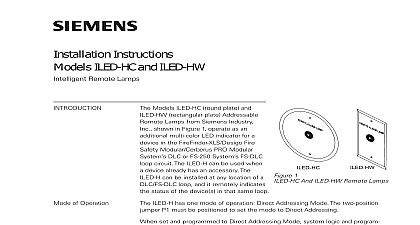
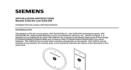
Installation Instructions ILED SC and ILED SW Remote Lamps Models ILED SC round plate and ILED rectangular plate Addressable Remote from Siemens Building Technologies shown in Figure 1 operate as an multi color LED indicator for a in the FS 250C System FDLC loop The ILED S can be used when a already has an accessory The ILED S be installed at any location of an FDLC and it remotely indicates the status of device s in that same loop 1 And ILED SW Remote Lamps of Operation ILED S has two modes of operation Mode and Direct Addressing Mode Use the two position jumper P1 to set mode set to Passive mode the ILED S remotely duplicates the on board LED status a device with the same address In Passive Mode the ILED S is not supervised cannot relay information to the panel set and programmed to Direct Addressing Mode the ILED S uses its own address to follow the status of a single device or a group of devices in the addresssable device circuit and Indicators LED indicator is capable of flashing any one of three distinct colors green or red In passive mode the ILED S continuously checks the information on loop for the device it is programmed to follow on the results of these checks the LED indicator flashes the following 315 048637C 3 Building Technologies Safety to Figure 2 for the location of the programming holes and jumper P1 Direct Addressing mode the LED on the ILED S is controlled by logic functions using the FS CT2 Tool In Direct Addressing Mode the ILED S blinks only Canada ILED Ss configured for Direct Addressing mode must be configured in FS CT2 Tool as follows HOLES 2 Printed Circuit Board Mode set the ILED S to Passive Mode follow the steps listed below the address of the device the ILED S will follow jumper P1 to position 2 and 3 the ILED S to the SDPU Device Programming Unit by inserting the from the SDPU cable provided with the SDPU into the programming on the ILED S board the instructions in the SDPU Manual P N 315 033260 to program ILED S to the desired address Record the device address on the label on the ILED S front panel jumper P1 to position 1 and 2 ILED S can now be installed and wired to the system Addressing Mode set the ILED S to Direct Addressing Mode follow the steps listed below the unique address of the ILED S jumper P1 to position 2 and 3 Building Technologies Safety 315 048637C 3 the ILED S to the SDPU Device Programming Unit by inserting the from the SDPU cable provided with the SDPU into the programming on the ILED S board the instructions in the SDPU Manual P N 315 033260C to program ILED S to the desired address Record the device address on the label on the ILED S front panel the FS CT2 Programming Tool assign the ILED S to an output zone When Input Group that is assigned to that Output Zone reports an off normal the ILED S will blink red if the reported event type matches the type selected for its zone For further information refer to the Programming Manual P N 315 049403C ILED S can now be installed and wired to the system BATTERY and AC prior to working on equipment to the wiring diagram in Figure 3 below to wire the ILED S ILED S is polarity insensitive Switching Line1 and Line2 has no effect on wire size AWG minimum AWG maximum larger than 14 AWG can damage the connector FDLC 3 The ILED S sure to program the ILED before installing the unit ILED S may be placed at any location on the FDLC loop Use a single gang box user supplied for mounting the ILED SW Use a 4 inch octagonal conduit user supplied for mounting the ILED SC Refer to Figure 4 for typical ILED S Building Technologies Safety 315 048637C 3 NOT REAR SUPPLIED 4 The ILED SW number of ILED S modules on the FDLC loop must be included in the total count intelligent field devices regardless of the mode for which the ILED S was set For restriction of the total number of devices in the FDLC loop refer to the FS 250C Operation and Maintenance Manual P N 315 049589C RATINGS Building Technologies Ltd Kenview Boulevard Ontario L6T 5E4 Canada Building Technologies Safety 315 048637C 3


