Siemens ILED-XC, ILED-XW Intelligent Remote Lamps with Dual Isolators, Installtion Instructions

File Preview
Click below to download for free
Click below to download for free
File Data
| Name | siemens-iled-xc-iled-xw-intelligent-remote-lamps-with-dual-isolators-installtion-instructions-4697312805.pdf |
|---|---|
| Type | |
| Size | 725.73 KB |
| Downloads |
Text Preview
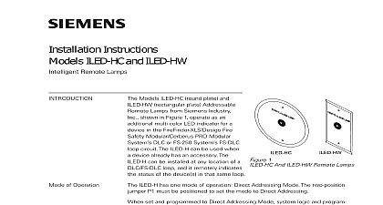
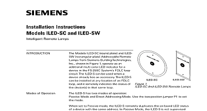
INSTRUCTIONS ILED XC and ILED XW Remote Lamps with Dual Isolators Models ILED XC round plate P N S54370 B6 A1 and ILED XW rectangular plate P N Addressable Remote Lamps from Siemens Industry Inc shown in Figure 1 It as an additional tri color LED indicator for a device in the device loop circuit of the Desigo and Cerberus PRO FC922 FC924 FV922 FV924 Fire Alarm The ILED X can be used when a device already has an accessory The ILED X can be at any location of a device loop and it remotely indicates the status of the device s in that loop 1 and ILED XW Remote Lamps OF OPERATION ILED X must have a unique address when it works in the device loop ILED X modules support two operation modes polarity insensitive mode and isolator mode The can be wired for either mode refer to Figures 3 and 4 During the isolator mode the built in isolators will work at both sides of the module to isolate the line short in front or behind the module AND INDICATORS LED indicator is capable of flashing any one of three distinct colors green yellow or red based on in the system configuration tool Observe precautions for handling Electrostatic Sensitive Devices Siemens Industry Inc Building Technologies Division The system logic and programming determine when and what color the ILED X will blink Intervals supervisory operation is in trouble power or need to be to Figure 2 for the location of the programming holes HOLES ARE POLARITY PLUG CAN BE INSERTED ANY DIRECTION 2 Printed Circuit Board program the ILED X follow the steps listed below Determine a unique address for the ILED X Connect the ILED X to the DPU Device Programming Unit by inserting the plug from the DPU cable with the DPU into the programming holes on the ILED X board at either direction polarity Follow the instructions in the DPU Manual P N 315 033260 to program the ILED X to the desired Record the device address on the label located on the back of the ILED X front panel Desigo FC2025 FC2050 FV2025 FV2050 and Cerberus PRO FC922 FC924 FV922 FV924 Fire Systems In the Configuration tool assign the ILED X to the output of a logic function For information refer to the Configuration Tool Manual of Desigo and Cerberus PRO FC922 FC924 FV922 FV924 Fire Alarm Document ID A6V10315023 The ILED X can now be installed and wired to the system Deactivate P2 circuit by either or both of the following Using the PMI bypass the circuit modified and or physically disconnect the circuit from the P2 source BATTERY and AC prior to working on equipment ILED X modules support two operation modes polarity insensitive mode and isolator mode The can be wired for either mode refer to Figures 3 and 4 the isolator mode the built in dual isolators will work at both sides of the module to isolate the line in front or behind the module the polarity insensitive mode switching Line1 and Line2 has no effect on performance wire size AWG minimum AWG maximum larger than 14 AWG can damage the connector O N E X T D D R E S S A B L E E V I C E O C O N T R O L PA N E L R P R E V I O U S D D R E S S A B L E D E V I C E I N E 1 I N E 2 I N E 1 I N E 2 3 polarity insensitive mode wiring O N E X T D D R E S S A B L E E V I C E O C O N T R O L PA N E L R P R E V I O U S D D R E S S A B L E D E V I C E I N E I N E I N E I N E 4 isolator mode wiring the device line up to 30 of any compatible devices in polarity insensitive mode with 20 ohms line resistance can be isolated between two modules in isolator mode in a Class A Style 6 the device line up to 30 of any compatible devices in polarity insensitive mode with 20 ohms line resistance can be isolated behind one module in isolator mode in a Class B Style 4 HLIM isolator module and SBGA 34 sounder base cannot be used in the same loop with the in isolator mode sure to program the ILED before installing the unit ILED X may be placed at any location on the device loop Use a UL listed recognized single gang box user supplied for mounting the ILED XW Use a UL listed recognized 4 inch octagonal box user supplied for mounting the ILED XC Refer to Figures 5 and 6 for typical ILED X NOT REAR SUPPLIED 5 the ILED XW 6 the ILED XC number of ILED X modules on the device loop must be included in the total count of intelligent field For the restriction of the total number of devices in the device loop refer to the device loop of the Desigo FC2025 FC2050 FV2025 FV2050 and Cerberus PRO Fire Alarm Systems RATINGS Voltage average current RMS 32 Vdc security disclaimer products and solutions provide security functions to ensure the secure operation of building comfort safety security management and physical security systems The security functions on these products and are important components of a comprehensive security concept is however necessary to implement and maintain a comprehensive state of the art security concept that customized to individual security needs Such a security concept may result in additional site specific action to ensure that the building comfort fire safety security management or physical security for your site are operated in a secure manner These measures may include but are not limited to networks physically protecting system components user awareness programs defense in depth additional information on building technology security and our offerings contact your Siemens sales or department We strongly recommend customers to follow our security advisories which provide on the latest security threats patches and other mitigation measures http www siemens com cert en cert security advisories htm Statement and usage of equipment not in accordance with instructions manual may result in of radio frequency energy to radio communications Read the following information and use equipment in accordance with instructions manual equipment generates uses and can radiate radio frequency energy and if not installed and used in accordance the instructions manual may cause interference to radio communications has been tested and found to comply with the limits for a Class A computing device pursuant to Part 15 of FCC Rules are designed to provide reasonable protection against such interference when operated in a commercial of this equipment in a residential area is likely to cause interference in which case the user at his own will be required to take whatever measures may be required to correct the interference PAGE HAS BEEN LEFT INTENTIONALLY BLANK Industry Inc Technologies Division Park NJ Canada Ltd North Service Road East ID A6V101055484 en a A5Q00062950 Ontario 0H6 Canada