Siemens LED-3 4 Remote Annunciator, Installation Instructions
File Preview
Click below to download for free
Click below to download for free
File Data
| Name | siemens-led-3-4-remote-annunciator-installation-instructions-7640598312.pdf |
|---|---|
| Type | |
| Size | 698.36 KB |
| Downloads |
Text Preview
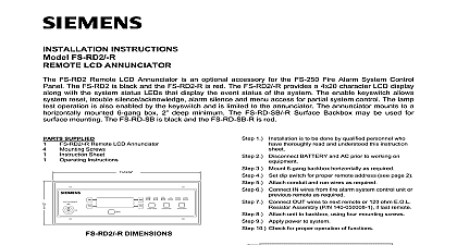
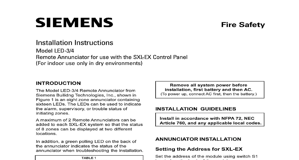
Fire Safety Instructions LED 3 4 Annunciator for use with the SXL EX Control Panel indoor use only in dry environments Model LED 3 4 Remote Annunciator from Builidng Technologies Inc shown in 1 is an eight zone annunciator containing LEDs The LEDs can be used to indicate alarm supervisory or trouble status of zones maximum of 2 Remote Annunciators can be to each SXL EX system so that the status 8 zones can be displayed at two different addition a green polling LED on the back of annunciator indicates the status of the when troubleshooting the installation 1 OPERATING Power VDC no LEDs on 10mA per TROUBLE LED max all LEDs on all system power before first battery and then AC power up connect AC first then the battery GUIDELINES in accordance with NFPA 72 NEC 760 and any applicable local codes INSTALLATION the Address for SXL EX the address of the module using switch S1 on the back of the module set address 1 SW1 of S1 to OFF SW2 SW6 of S1 to ON set address 2 SW2 of S1 to OFF SW1 and SW3 SW6 to ON other setting causes a trouble indication on panel There also would be no activity from annunciator or from the polling LED DS17 is located next to the S1 switch the system wiring to the TB1 terminals the annunciator module Refer to Table 2 3 and Figure 2 for proper wiring connec and cable length 1 Remote Annunciator Building Technologies Inc Fernwood Road Park New Jersey 07932 315 093066 11 Building Technologies Ltd Kenview Boulevard Ontario L6T 5E4 Canada After the system is tested tighten the mount screws Fill in the appropriate information for each on the card provided THE SXL EX SYSTEM THE LED 3 4 MODULE the Program Mode level 9 of the programming mode Press the RESET and DRILL keys at the time The TROUBLE LED lights and letter E appears on the seven segment Enter the password by pressing appropriate keys 1 3 2 SILENCE 4 press the SILENCE key seven segment display either shows F to an incorrect password or A to that the password is accepted If the F appears repeat Steps 1 and 2 If the A appears continue to the next step Press the ACK key once to enter the Pro mode The PROGRAM TEST LED on front panel lights and the seven segment shows the letter P 2 Connections Provides power to circuitry Serial communication line Return line Earth Return 3 Cable Length vs Wire Size Length feet feet feet the wiring polarity when making con Damage may result from incorrect wiring Mount the annunciator semiflush using a gang electrical backbox DO NOT tighten the mounting screws since module may have to be removed during when looking for activity the polling LED DS17 on the back of module Limited UL listed Panel Port TB 3 Limited 4 and Negative Fault at 20K for on TB 1 ER ER LED LED 2 Wiring Connections 2 Press the RESET key nine times to select Before testing you MUST notify the level 9 to program the LED 3 4 press the SILENCE key to select level 9 level 9 has only one sublevel Enable Disable SRC 8 and LED 3 4 sublevel is displayed on the seven segment following the hyphen To select the sublevel press the SILENCE key as Select the device according to the table Zone 1 LED Zone 2 LED Zone 3 LED Initiating Device Circuit No 1 No 2 See SXL EX Manual P N 315 095997 for enable disable the LED 3 4 Press the RESET key to advance the IDC LED to the desired device Press the DRILL key to enable or disable the The ALARM LED indicates the enable status the LED is ON the LED 3 4 enabled exit the Program mode Press the ACK key until the PROGRAM LED turns off Continue to press ACK until the letter L on the seven segment display Then press the SILENCE key to exit the Program Mode Panel AND TESTING module periodic maintenance is required however Building Technologies Inc recom periodic testing in charge of the Fire Alarm since the test may disrupt normal operations In addition you notify the local Fire Department if department is connected to the tie Operation the annunciator for alarm operation by Activating an initiating device on a zone for alarm Confirming the normal alarm functioning of unit and the Control Panel ALARM LED LED on left should glow red the appropriate zone Operation the annunciator for supervisory operation by Activating an initiating device on a zone for supervisory Confirming the normal supervisory functioning the unit and the Control Panel SUPERVISORY LED LED on left should yellow for the appropriate zone Operation the annunciator for trouble operation by Disconnecting a wire from a zone at the Confirming the normal trouble functioning of unit and the Control Panel TROUBLE LED LED on right for the zone should glow yellow Supervision annunciator supervision by Disconnecting the DATA line from TB1 on The Control Panel indicates the trouble but there are two annunciators on the system does not tell which of the two is in trouble more information on this supervision see section on Troubleshooting on page 4 Test the Test Mode the LED 3 4 Module Lamps test the LEDs on the LED 3 4 module for set the address on Switch S1 as below exit the test mode first press the ACK key until PROGRAM TEST LED turns off and the letter appears on the seven segment display Then the SILENCE key CALCULATIONS backup is required for the LED 3 4 To the size battery you need use the calculation table in the SXL EX Manual 315 095997 an LED fails to respond Check DS17 on the back of the module for If there is no activity it means there a module with possible problems such as address missing or incorrect no power at the module or some problem Remove the module from its backbox to the DS17 LED Do not touch the terminals to anything or damage result Check the control panel for proper annuncia of the alarm supervisory or trouble Check the wiring between the module and control panel Check the address setting on switch S1 is located on the back of the module the module from its backbox to S1 Check that there are 24 volts between the terminals 24V and V the problem continues replace the module Check the new module for correct wiring and the address settings on S1 before up the system Fault Code 8 appears on the SXL EX The module is connected but is not configured to the LED 3 4 Programming instructions The module is configured but is not connected to the LED 3 4 Annunciator instructions Check the module for an error in wiring testing is complete reset Switch S1 to the address setting for the module the Test Mode for SXL EX level 5 of the test mode Press the RESET and DRILL keys at the time The TROUBLE LED lights and letter E appears on the seven segment Enter the password by pressing the appropri keys 1 2 3 4 press the SILENCE key seven segment display either shows F to an incorrect password or A to that the password is accepted If the F appears repeat Steps 1 and 2 If the A appears continue on to the next step Press the ACK key twice to enter the Test The PROGRAM TEST LED on the panel lights and the seven segment shows the letter t Select test level 5 for the Lamp Test by the RESET key five times then the SILENCE key level 5 has two sublevels Local display lamp test Remote display