Siemens LIM-1 Line Isolator Module, Data Sheet

File Preview
Click below to download for free
Click below to download for free
File Data
| Name | siemens-lim-1-line-isolator-module-data-sheet-2401867395.pdf |
|---|---|
| Type | |
| Size | 935.16 KB |
| Downloads |
Text Preview
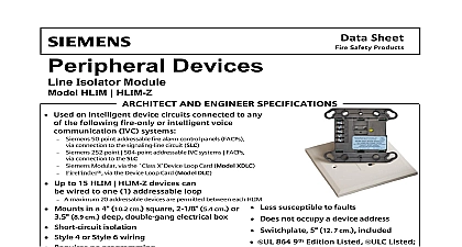
Data AND ENGINEER SPECIFICATIONS MXLV Isolator Module LIM 1 Used on MXL intelligent device circuits Up to 12 of Model LIM 1 per ALD circuit Short circuit isolation Increased fault tolerance Style 4 or Style 6 wiring Requires no programming Does not occupy a device address Local light emitting diode LED indicator Mounts in a 4 or double gang electrical box Cover plate included UL 864 9th Edition Listed and ULC Listed CSFM NYMEA Approved Overview Line Isolator Module Model LIM 1 provides protection on MXL intelligent device ALD When a short circuit is detected LIM 1 isolates the affected segment on the allowing the remaining devices to operation LIM 1 is self restoring automatically to circuit segment when the fault removed and includes a yellow LED which to indicate the device has been Model LIM 1 mounts in either a 3 or double gang box and is supplied with a cover plate a circular opening for the LED LIM 1 can be wired in either a Style 4 or 6 configuration Model LIM 1 does not a device address on the ALD circuit and not require any programming to 12 Model LIM 1 modules may be installed each ALD circuit isolation shall be provided for all circuits The isolator shall in a 4 or double gang box and shall include a yellow LED to activation The isolator shall also include cover plate with an opening for the LED isolator Model LIM 1 shall be a self restoring that shall neither require programming occupy an address on the intelligent device The isolator shall be capable of being in either Style 4 or Style 6 wiring Ratings Power Line Resistance each Model LIM 1 Module 500 max ohms Industry Inc Technologies Division Line Isolator Module 5040 and Humidity Range LIM 1 is UL 864 9th Edition Listed for dry locations within a temperature of 120 3 49 2 to 32 3 and a relative humidity range of at a temperature of 90 3 Diagram Class B Installation Model LIM 1 and Operation Manuals Note For further details refer to MXL IOM manual 315 092036 Line Isolator Module ALD Documentation Sheet Number for Ordering Description Line Isolator Module ALD All wiring must comply with local and national electrical codes Do not install more than 20 devices on a single Model LIM 1 module Minimum wire gauge is 18 AWG The total wire resistance both wires between each Model LIM 1 exceed 20 ohms Do not install more than 12 Model LIM 1 modules per ALD loop All circuits supervised Refer to the MXL MXLV manual p n 315 092036 for the full of compatible devices Diagram Class A Single Loop Installation LIM 1 All wiring must comply with local and national electrical codes Do not install more than 20 devices between any two 2 Model LIM 1 Minimum wire gauge is 18 AWG The total wire resistance both wires between each Model LIM 1 exceed 20 ohms Do not install more than 12 Model LIM 1 modules per ALD loop All circuits supervised Refer to the MXL MXLV manual p n 315 092036 for the full of compatible devices Diagrams Installation Use a standard 3.5 inch deep double gang electrical switchbox or a electrical box that is 2 deep Connect the field wiring Press Model LIM 1 into the box and fasten module plate to the box Cover the module front plate with the plate supplied and fasten the with the supplied screws This marketing data sheet is not intended to be used for system design or installation purposes the most up to date information refer to each product installation instructions Industry Inc Technologies Division Safety Fernwood Road Park NJ 07932 973 593 2600 908 547 6877 www SBT Siemens com FIS in U S A Safety Kenview Boulevard Ontario 5E4 Canada 905 799 9937 905 799 9858 2011 sheet dated 4 03