Siemens LIM-1 Loop Isolator Module, Installation Instructions
File Preview
Click below to download for free
Click below to download for free
File Data
| Name | siemens-lim-1-loop-isolator-module-installation-instructions-7951024368.pdf |
|---|---|
| Type | |
| Size | 733.46 KB |
| Downloads |
Text Preview
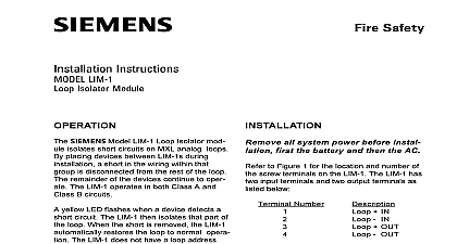
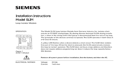
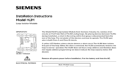
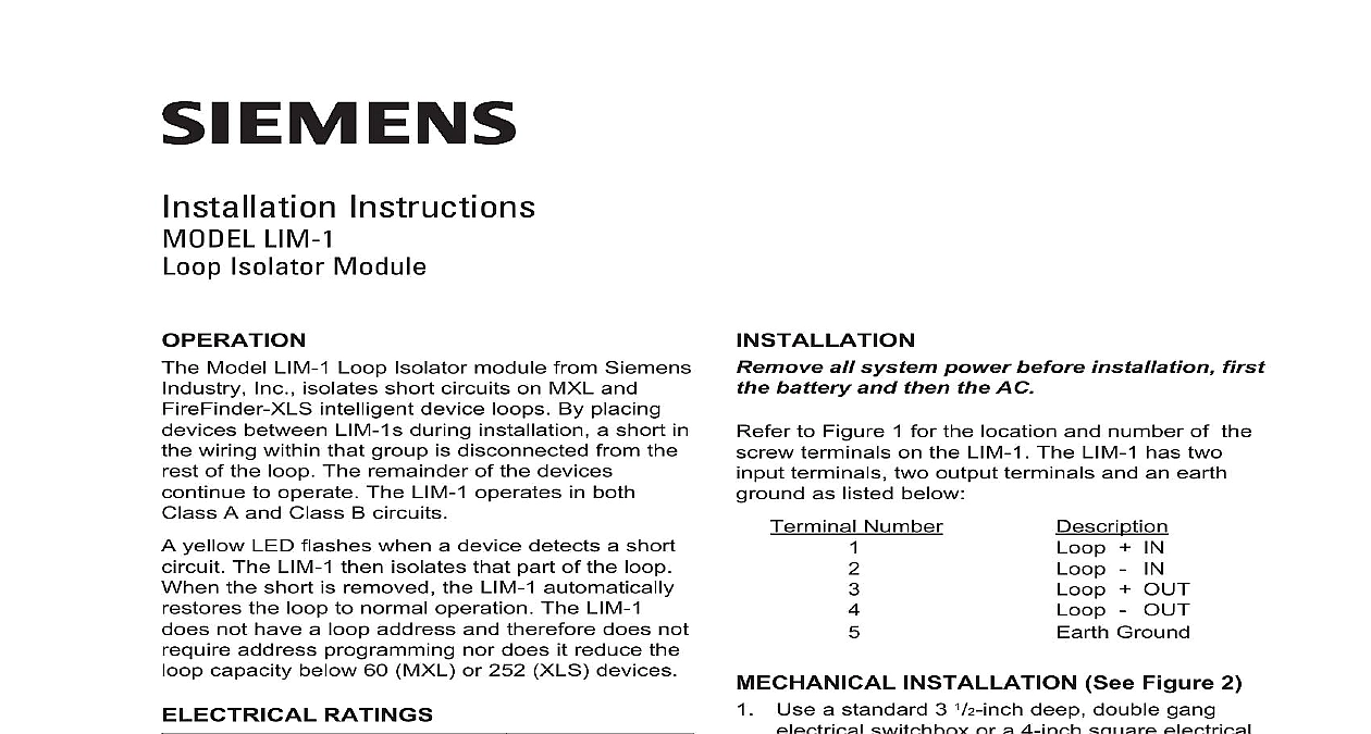
Installation Instructions LIM 1 Isolator Module Model LIM 1 Loop Isolator module from Siemens Inc isolates short circuits on MXL and intelligent device loops By placing between LIM 1s during installation a short in wiring within that group is disconnected from the of the loop The remainder of the devices to operate The LIM 1 operates in both A and Class B circuits yellow LED flashes when a device detects a short The LIM 1 then isolates that part of the loop the short is removed the LIM 1 automatically the loop to normal operation The LIM 1 not have a loop address and therefore does not address programming nor does it reduce the capacity below 60 MXL or 252 XLS devices RATINGS 1 LIM 1 Industry Inc Technologies Division Park NJ 315 049552 6 all system power before installation first battery and then the AC to Figure 1 for the location and number of the terminals on the LIM 1 The LIM 1 has two terminals two output terminals and an earth as listed below Terminal Number IN OUT OUT Ground INSTALLATION See Figure 2 Use a standard 3 1 2 inch deep double gang switchbox or a 4 inch square electrical that is 2 1 8 inches deep Connect the field wiring Press the LIM 1 into the and fasten the module plate to the box Cover the module front plate with the plate and fasten with screws supplied SQUARE BOX 1 8 INCHES DEEP GANG BOX 1 2 INCHES DEEP SQUARE SQUARE 2 the LIM 1 Canada Limited Technologies Division Kenview Boulevard Ontario L6T 5E4 Canada LIM 1 may be used in two circuit configurations B See Figure 3 Class B wiring each LIM 1 isolates a branch on the Note that a short on the main branch causes entire loop to fail To prevent this mount the at the MXL or FireFinder XLS enclosure and each branch independently for Figure 3 All wiring must comply with national and local codes order to provide adequate protection it is recommended you do not install more than 20 devices on a single LIM 1 Minimum wire gauge is 18 AWG The total wire resistance both wires between LIM 1s exceed 10 ohms Do not install more than 12 LIM 1s per loop All circuits are supervised Refer to the MXL MXLV Manual P N 315 092036 the MLC Instructions Document ID A6V10328217 or the Installation Instructions Document ID A6V10239107 the list of compatible devices All terminals are power limited LOOP WHEN USING THE WITH THE DLC FOLLOWING MUST BE AT THE LIM 1 LINE 1 LINE 2 EARTH OUT 3 Wiring Diagram B Installation A Single Loop See Figure 4 Class A wiring the LIM 1s are wired in series with loop wiring This results in a single continuous If any group in the loop has a short that group is and a Class A circuit failure results The MXL or displays communication errors for the and a Class A failure for the loop itself for Figure 4 All wiring must comply with national and local codes order to provide adequate protection it is recommended you do not install more than 20 devices on a single LIM 1 Minimum wire gauge is 18 AWG The total wire resistance both wires between LIM 1s exceed 10 ohms Do not install more than 12 LIM 1s per loop All circuits are supervised Refer to the MXL MXLV Manual P N 315 092036 the MLC Instructions Document ID A6V10328217 or the Installation Instructions Document ID A6V10239107 the list of compatible devices All terminals are power limited WHEN USING THE LIM 1 WITH THE THE FOLLOWING POLARITY MUST BE AT THE LIM 1 LINE 1 LINE 2 ENCLOSURE ANALOG RETURN ANALOG FEED IN OUT OUT IN OUT OUT EARTH IN OUT OUT EARTH 4 Wiring Diagram A Installation Single Loop 315 049552 6 ID A6V10239166