Siemens MLC MXL Line Card, Installation Instructions
File Preview
Click below to download for free
Click below to download for free
File Data
| Name | siemens-mlc-mxl-line-card-installation-instructions-0487653192.pdf |
|---|---|
| Type | |
| Size | 752.35 KB |
| Downloads |
Text Preview
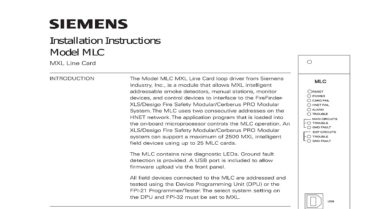
Installation Instructions MLC Line Card FAIL FAIL CIRCUITS FAULT CIRCUITS FAULT Model MLC MXL Line Card loop driver from Siemens Inc is a module that allows MXL intelligent smoke detectors manual stations monitor and control devices to interface to the FireFinder Fire Safety Modular Cerberus PRO Modular The MLC uses two consecutive addresses on the network The application program that is loaded into on board microprocessor controls the MLC operation An Fire Safety Modular Cerberus PRO Modular can support a maximum of 2500 MXL intelligent devices using up to 25 MLC cards MLC contains nine diagnostic LEDs Ground fault is provided A USB port is included to allow upload via the front panel field devices connected to the MLC are addressed and using the Device Programming Unit DPU or the Programmer Tester The select system setting on DPU and FPI 32 must be set to MXL MLC initializes operates and maintains all devices on the loop The MLC communicates all relevant and event information such as alarms and troubles the PMI PMI 2 PMI 3 XLS FCM2041 U2 Desigo Fire Modular FCM2041 U3 Cerberus PRO Modular sensitivity of any intelligent smoke detector and the functions of any intelligent output devices can be and adjusted from the PMI PMI 2 PMI 3 XLS Desigo Fire Safety Modular FCM2041 U3 PRO Modular through the MLC All information the devices on the loop can be displayed on the PMI XLS FCM2041 U2 Desigo Fire Safety FCM2041 U3 Cerberus PRO Modular To see available information for each device on the loop refer the FireFinder XLS IOM Manual P N 315 033744 the Fire Safety Modular IOM Document ID A6V11231620 or the Cerberus PRO Modular IOM Document ID A6V11231627 1 Line Card MLC supports two separate circuits of MXL intelligent field devices Each circuit monitor and control up to 60 intelligent devices as well as device accessories bases audible bases and remote lamps in any combination Each circuit has a address on the HNET network The installer sets the address on the module the first circuit which can be either odd or even A consecutive address is auto assigned to the second circuit internally Inc Inc Inc Industry Inc Inc TTTTTececececechnologies Di Di Di Division Di on board microprocessor provides the MLC with the ability to function and alarm conditions even if the PMI PMI 2 PMI 3 XLS FCM2041 U2 Desigo Safety Modular FCM2041 U3 Cerberus PRO Modular fails and Indicators front panel of the MLC contains one reset switch 9 LEDs and three HNET switches as shown in Figure 1 Pushing the reset switch re initializes the operation MLC must be re initialized by pushing the module Reset switch any time the supply is interrupted LED functions are defined as follows FAIL FAIL CIRCUITS TROUBLE CIRCUITS GND FAULT ON When illuminated the power for the MLC is to the card OFF When illuminated hardware failure on the or unsuccessful firmware During firmware upload this should blink OFF When illuminated that the HNET communica with the MLC has terminated OFF When illuminated that the MLC has detected alarm OFF When illuminated that a trouble is present on MLC that is not related to its wiring or slave ALD driver OFF When illuminated that the MLC has detected wiring trouble fault on device loop or 2 OFF When illuminated that the MLC has detected ground fault on device loop 1 or 2 wiring CIRCUITS TROUBLE Yellow Normally OFF Not used at this time CIRCUITS GND FAULT Yellow Normally OFF Not used at this time Industry Inc Technologies Division following components must be set prior to inserting the card into the CC 5 CC 2 to Figure 2 MLC uses two module addresses in the HNET network Set the lower of the consecutive three digit HNET network addresses odd or even for the MLC the three rotary dial switches located near the bottom of the front panel Refer Figure 1 for the location of the switches The address for the MLC must be the as the address selected for it in the Zeus Programming Tool To set the address the pointers on each of the three dials to the numbers for the selected address example if the address is 123 set the pointer for the HUNDREDS dial to set pointer for the TENS dial to and set the pointer for the ONES dial to The of allowable addresses is from 001 to 251 leading zeros must be used all system power before installation first battery then AC To power up the AC first then the battery MLC plugs perpendicularly into one slot in the CC 5 CC 2 card cage via two 96 DIN connectors and can occupy any slot in the card cage Refer to Figure 2 the MLC card into the card guides rightside up lettering on the front panel is the card in until the card edge connectors contact the on the motherboard that the DIN connectors of the card and the card cage properly The card can only plug in one direction to the cage if it does not align DO NOT FORCE the card thumbs on the front panel adjacent to the captive and gently apply even pressure on the card until the seat in the receptacles on the motherboard with the captive screws 2 The MLC UPGRADES MLC is shipped with the latest firmware and the user should not have to unless suggested to do so by Siemens Industry Inc Technical Support time to time modules used in XLS Desigo Fire Safety Modular Cerberus PRO systems are upgraded to improve their operation or to add to their capabili with new features Firmware in the MLC is field upgradable Refer to the Zeus Manual P N 315 033875 and Zeus Help for additional details one end of a user supplied USB A to B cable into the USB port on the of the MLC Plug the other end into the host PC Zeus select the module to be upgraded in the Physical Tree Then select Build Transfer Module Firmware to Panel menu Industry Inc Technologies Division Firmware via USB Port dialog displays a list of available firmware for the module Select the firmware to be transferred the module by depressing the reset switch with a pointed object as a pencil The power and card fail LEDs should be blinking on Transfer to begin the module firmware transfer the Transfer button is not pressed within 30 seconds of resetting the MLC the will revert back to operation mode the transfer is completed click on the status the USB cable and reset the module button to view the transfer check for the current version of MLC software in an installed MLC go to the PMI XLS FCM2041 U2 Desigo Fire Safety Modular FCM2041 U3 PRO Modular and press the Menu button select Report press the More button and select the MLC at that address Press the Configuration soft key Appl Rev for the Application Version and press View MLC Software Version field wiring to the MLC is connected to the terminal blocks of the CC 5 CC 2 card slot in which it is installed Connect External Wiring the screw of the terminal by turning it counterclockwise the wire into the side of the terminal block the screw of the terminal block by turning it clockwise 1 2 NOT USE SLOT OF CC 5 CC 2 NOT USE 24VDC FROM THE PSC 12 3 The 24VDC Power Lines To The MLC Slot In The CC 5 CC 2 Industry Inc Technologies Division 24V from the PSC 12 PSX 12 to terminal 17 and 24V from the PSC 12 to terminal 18 of the slot in the CC 5 CC 2 where the MLC will be installed to Figure 3 device loop circuit can be wired Class B or Class A MLC field circuit wiring not require twisted shielded wire It can be installed in conduit containin