Siemens MOI-7 Annunciator Driver, Installation Instructions

File Preview
Click below to download for free
Click below to download for free
File Data
| Name | siemens-moi-7-annunciator-driver-installation-instructions-6459312870.pdf |
|---|---|
| Type | |
| Size | 760.50 KB |
| Downloads |
Text Preview
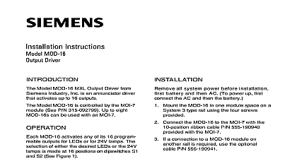
Installation Instructions MOI 7 Annunciator Driver Model MOI 7 from Siemens Industry Inc is an network module that connects to a annunciator using MOD 16s and MID 16s MOI 7 can support up to 8 MOD 16s and 8 which provide for a total of 128 open outputs and 128 user programmable These inputs and outputs are controlled by functions in the CSG M MOI 7 has two LEDs that indicate the status the MXL MXL IQ network interface The LED blinks every time the MOI 7 with the MXL MXL IQ The LED goes on steady if the MOI 7 communicate with the MXL MXL IQ additional information on the MXL MXLV refer to the MXL MXLV Manual 315 092036 all system power before installa first battery and then AC To power up the AC first then the battery Mount the MOI 7 MOI 7 mounts on a System 3 rail in two spaces Mount the MOI 7 using the screws provided Set the network address on S1 MOI 7 occupies one network address in MXL MXL IQ System Set the address to Table 1 so that it agrees with address assigned in the CSG M the network address of the MOI 7 is 127 or the lamp test for the MOD 16 is performed in one MOD 16 at a time the network address of the MOI 7 is 128 or the lamp test is performed by energizing all MOD 16s simultaneously compliance with UL 864 effective May 1 1995 power limited fire protective signaling conduc must be separated a minimum of 1 4 inch from of the following items located within a control electric light power Class 1 or non power limited signaling con meet these requirements the following must be observed when installing and wiring to this control panel If power limited wiring is not used within enclosure the following guidelines not apply In that case be sure to standard wiring practices ENTERING THE ENCLOSURE Limited Wiring to the following module terminations within the enclosure and shown in Table 2 considered non power limited and must enter the knockouts specified See Figure 1 between the knockouts specified and the termination must be in the shortest route must not overlap any other wiring Industry Inc Technologies Division Park NJ 315 092799 8 Building Technologies Ltd Safety Security Products Kenview Boulevard Ontario 5E4 Canada IN THE ENCLOSURE Limited Wiring following wiring is considered non power and must be routed as shown in Figure 1 To the PS 5A TB1 Positions 2 3 from the terminals 5 6 Directly from the MMB or PSR 1 and between PS 5A J3 and the MOI 7 P1 ENTERING THE ENCLOSURE Limited Wiring to the terminations shown in Table 3 is power limited and must enter through knockouts specified See Figure 1 Wiring the knockout specified and the module must be in the shortest route and not overlap any other wiring 3 1 4 or 7 1 Power Limited Wiring RATINGS MOD 16 and MID 16 CONNECTIONS MOI 7 is shipped with two cables See 2 5V Power MOI 7 receives its 5 volt power on P1 This power can be sent to modules requiring 5 volts from P2 Pin 1 the positive input pin 2 the return Use P N 600 291261 which is supplied MXL Network Connection MOI 7 can be connected to the MXL in three ways See Figure 3 first connection is for Style 4 For Style 4 use only terminals 1 and 2 of TB1 3 and 4 of TB1 are not used In a 4 network make only Network A and ignore all Network B See Figure 3 second connection allows the MOI 7 to directly to a Style 7 network This is called a Remote Style 7 In this all the terminals of TB1 are Install the MOI 7 at any point along the 7 network except at either end The 7 network must terminate on an NET 7 to insure proper supervision of the Each MOI 7 connected directly to network wiring occupies one of the 32 nodes Do not use connector P5 in configuration See Figure 3 third connection is also Style 7 This is called a Local Style 7 and its is that it does not use up a node In this configuration the MOI 7 through the NET 7 installed in enclosure In order for the MOI 7 to use NET 7 it must connect to the 8 wire cable on either the MMB or the PSR 1 connector P5 This limits the distance MOI 7 can be located from the MMB or PSR 1 An eight foot cable P N MER 8 available for this purpose The MOI 7 must located in a close nippled enclosure ICs U1 and U12 and make no to TB1 See Figure 3 MXL IQ Network Connection MXL IQ provides Style 4 only for the Use only terminals 1 and 2 of TB1 all Network B wiring See