Siemens MOM-4 Optional Card Cage Module, Installation Instructions

File Preview
Click below to download for free
Click below to download for free
File Data
| Name | siemens-mom-4-optional-card-cage-module-installation-instructions-6097384512.pdf |
|---|---|
| Type | |
| Size | 790.67 KB |
| Downloads |
Text Preview
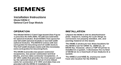
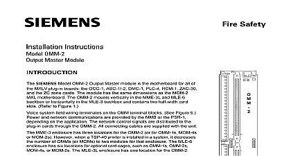
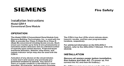
OPERATION all system power before first battery and then AC power up connect the AC first the battery the MOM 4 and its attached back Inspect it looking for such things as not properly installed dirt and material on the board Instructions MOM 4 Card Cage Module Model MOM 4 Card Cage board See 1 provides the MXL MXLV MXL IQ with card slots for optional modules Each MOM has space for two full width optional modules four half width modules or a combination of full and two half width optional modules The comes with four card guides for mount two full width modules The half width mod come with the necessary extra card guides mounting them The MME 3 enclosure has up to three for the MOM 4 or for OMM 2s or MOM 2s when a TSP 40 printer is in an enclosure it de the number of MOM 4s to a of two modules in that MSE 3L has one location for the MOM 4 provides two power connector recep two power connection terminal blocks and data connector receptacles A 24 VDC cable provides the main power used by the optional and an 8 wire ribbon cable for connection 5 VDC and data lines are provided with the installation kit TB5 is 24 VDC output only with a of 2A Industry Inc Technologies Division Park NJ 315 090852 13 24 VDC 24 VDC 1 Card Cage Building Technologies Ltd Safety Security Products Kenview Boulevard Ontario 5E4 Canada installation kit for the MOM 4 includes the items mount the MOM 4 card cage in an enclosure 10 nuts 10 flat washers 10 lockwashers card guides 2 wire cable P N 555 190969 8 conductor ribbon cables P N and P N 555 193344 Place the module vertically on the mounting near the top left of the enclosure as in Figure 3 Fasten the MOM 4 in position with the provided to Figure 2 mount the MOM 4 card cage in an enclosure MOM 4 mounts vertically on the lower of the MBR MP mounting plate under MMB or the PSR on the four studs provided shown in Figure 2 Place the module on the mounting studs in left hand position of the mounting plate Fasten the MOM 4 in position with the provided as shown in Figure 2 To mount any other MOM 4 modules used in system repeat the above steps Use the or right hand position for the modules as needed Once the MOM 4 is secured install the four guides included in the package the MOM 4 on an MBR MP 2 Plate the MOM 4 in an MSE 3L Enclosure 3 the Card Guides in the MOM 4 4 install the card guides See Figure 4 the MOM 4 is secured install the four guides included in the package Mount the card guides to the positions shown in 4 The MOM 4 is shipped with mounting for the card guides already installed the other end of the cable to P10 on the again making sure that the locking rib of cable engages the locking tab on P10 This supplies 5 VDC and communication be the MMB or SMB and the MOM 4 Slip the slot in the base of the card guide one of the mounting screws Make sure that the locating pin on the guide seated in the hole on the MOM 4 Tighten the screw this process for the remaining card The MOM 4 is now ready to accept the modules Installation are two inputs that connect the MOM 4 the MMB or SMB These inputs provide all necessary power and data lines to support optional modules first input is an 8 conductor ribbon cable the cable to P6 on the MMB or SMB sure that the locking rib on the cable engages the locking tab on P6 second input feeds 24 VDC full wave unfil DC to the MOM 4 This input connects to P8 MMB 1 or SMB 1 only or TB6 A 2 wire is provided for backward compatability with MMB 1 or SMB 1 Connect one end of the cable P3 on the MMB 1 or SMB 1 making sure the rib and board tab lock Attach the other end the cable to P8 on the MOM 4 in the same way the 24 VDC is provided by either the or SMB 2 or the PSR 1 use TB6 on the to connect the power The wire for this is not supplied See MMB 2 Installa Instructions P N 315 095097 or PSR 1 Instructions P N 315 090911 for connections power source on the MOM 4 is limited to 2A by the MMB 1 or SMB 1 Under maximum conditions the optional modules must never more than 2A from this connection the 24 VDC is provided by either the or SMB 2 use TB6 on the MOM 4 to the power The wire for this connection is supplied See the MMB 2 Installation Instruc P N 315 095097 the MMB 3 Installation P N 315 048860 or the SMB 2 Instructions P N 315 095931 the system includes an MMB 2 3 or the maximum load current for the MOM 4 6A when using an MPS 6 and 12 amps when an MPS 12 However the 6A must be by the amount of current being used by CZM 1 PS 5A 5N7 and NAC outputs Thus the full 1A available to the CZM 1 and and the 3A available to the NAC are used derate the MOM 4 current to 2 or if an MPS 12 is used derate the MOM 4 to 8A the 24 VDC is provided by PSR 1 use on the MOM 4 to connect the power The for this connection is not supplied See the Installation Instructions P N 315 090911 terminal connections the system includes a PSR 1 the maximum current for the MOM 4 is 6A when using an and 12 amps when using an MPS 12 the 6A must be reduced by the amount of being used by the CZM 1 and PS 5A 5N7 Thus if the full 2A available to the CZM 1 PS 5A 5N7 are used derate the MOM 4 to 4A or if an MPS 12 is used derate the current to 10A on the optional modules installed power may be available at TB5 and for appliances See Table 1 for the current required by each module under load conditions which optional plug in modules are used your CSG M configuration Depending on the modules used determine the outstanding by using Table 1 See the EXAMPLE This can be used for notification appliances or the optional power connector on TB5 Industry Inc Technologies Division Park NJ 315 090852 13 When a CSM 4 is used you may add appliances to it if the maxi load current to the MOM 4 does exceed 2 amps MMB 1 or SMB 1 with an MMB 2 3 SMB 2 or PSR 1 6 MPS 6 or 12 amps MPS 12 the total alarm current on each notification appliance circuit when the calculations load current 0.075 0.034 0.109A CRM 4 and one CSM 4 MPS 6 Available Current 0.109 1.891A MMB 1 or SMB 1 0.109 5.891A PSR 1 MMB 2 3 SMB 2 no CZM 1 PS 5A 5N7 or NAC load MPS 12 Available Current 0.109 1.891 MMB 1 or SMB 1 0.109 11.891 PSR 1 MMB 2 3 SMB 2 with no CZM 1 PS 5A 5N7 or NAC load remaining current may be used for alarm notifica appliances Building Technologies Ltd Safety Security Products Kenview Boulevard Ontario 5E4 Canada