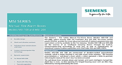
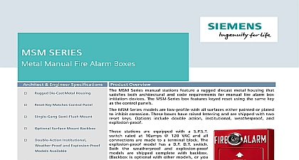
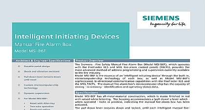
Siemens MS-51, MS-501 MS Series Manual Fire Alarm Box, Data Sheet

File Preview
Click below to download for free
Click below to download for free
File Data
| Name | siemens-ms-51-ms-501-ms-series-manual-fire-alarm-box-data-sheet-8157936420.pdf |
|---|---|
| Type | |
| Size | 843.17 KB |
| Downloads |
Text Preview
Sheet Safety Security Products Detection Devices Series Single Action Manual Fire Alarm Boxes MS 51 MS 501 AND ENGINEER SPECIFICATIONS Durable plastic design Shock and vibration resistant Activation visibly noticeable Optional contact arrangements No break rods necessary Surface or semi flush Options include key switch alarm lamp Meets ADA guidelines UL Listed FM CSFM NYCFD Approved Overview manual fire alarm boxes by Siemens Inc Fire Safety Models MS 51 and have been designed with extreme in order to meet an array of system requirements and operation sequences aforementioned models operate in a single action which utilizes a action The for each fire alarm box locks in the until the box is reset single action box which shall be of the non code shall consist of a molded housing fitted with a lever which when operated locks in after releasing a spring loaded contact switch activate the alarm circuit MS 51 and MS 501 contain one 1 normally contact NC which is intended for use with Fire Safety low voltage systems These 2 manual boxes can also be used for connection existing fire alarm systems of other manufacturers Electrical Ratings below for more details station key switch Specifications station MS 51 and MS 501 are constructed of durable polycarbonate material matte finish in red raised lettering in white The housing for the action box accommodates a lever when operated locks in position after a spring loaded contact switch Restoring the to normal can only be accomplished by the cover of the hinged housing with an Allen and then closing locking its cover housing for the double action box in addition the single action box incorporates a tab tab must initially be operated in order to permit to the lever body of the manual box shall be hinged to a back assembly to which it is locked with an Allen head Resetting the box after operating shall require the box momentarily and then locking the to the back plate shall be made for surface or semi flush to conduit boxes Series Conventional Detection Devices 6183 Industry Inc Technologies Division Diagrams Place the bottom of the box between 4 and 6 feet above the floor Distribute the manual fire alarm boxes throughout the protected area so that they are unobstructed readily accessible located in the normal exit path from the area NFPA 101 the National Building Code of Canada or local codes Provide additional boxes on each floor to obtain a maximum horizontal travel distance of 200 feet to the nearest box NFPA 101 the National Building Code of Canada or local codes Diagrams Model for Ordering Manual Station Key Package 500 620503 Manual Station N O SPST 500 688458 Manual Station N O SPST 500 620522 Double Action Manual Station 500 694511 Explosion Proof Manual Station 310 087863 Series Surface mount box 500 688901 Adapter Plate 545 520627 SB 5K MTG KIT SB 5R 310 019860 MFS Enclosure In these configurations in and out wires of zone loop must be separately as shown Do not wrap wire around any terminal Ratings Box Contact Ratings SPST NC SPST with key switch station 28 VAC DC 28 VAC DC SPST SPST 28 VAC DC 28 VAC DC 28 VAC DC SPST Accessories This marketing data sheet is not intended to be used for system design or installation purposes the most up to date information refer to each product installation instructions Industry Inc Technologies Division Safety Fernwood Road Park NJ 07932 973 593 2600 908 547 6877 www usa Siemens com Fire Safety Kenview Boulevard Ontario 5E4 Canada 905 799 9937 905 799 9858 in U S A 2012 sheet dated 10 02 1


