Siemens MS TP BIM Data Sheet

File Preview
Click below to download for free
Click below to download for free
File Data
| Name | siemens-ms-tp-bim-data-sheet-0723841596.pdf |
|---|---|
| Type | |
| Size | 2.16 MB |
| Downloads |
Text Preview
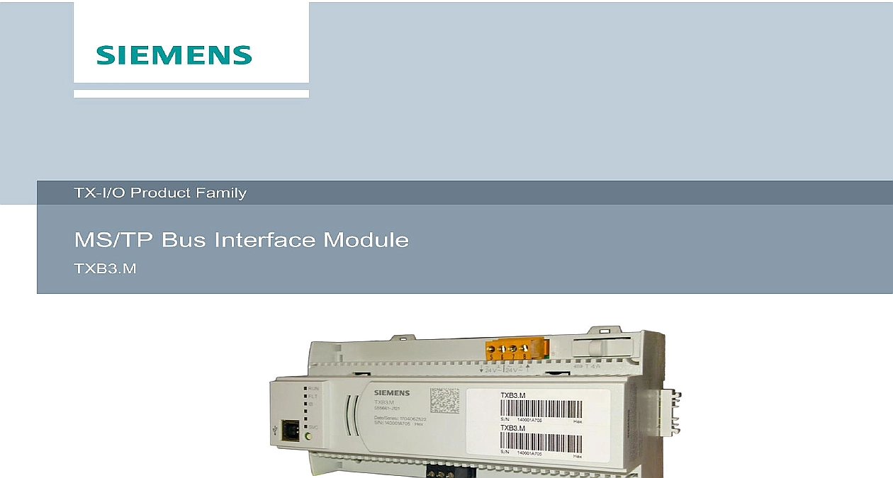
Product Family Bus Interface Module The BACnet MS TP Bus Interface Module TXB3 M enables communication between Field Level Network and TX I O modules Furthermore the BACnet MS TP BIM power for TX I O modules and peripheral devices Bus Interface Module to connect TX I O Modules to MS TP FLN Power supply for TX I O Modules and peripheral devices BACnet MS TP communication BTL certified Operating voltage AC 24 V USB interface Plug in screw terminals Mounting on standard DIN rails or on the wall Infrastructure Support up to 8 TX I O modules Support for 80 TX I O points Generation of 24 Vdc at 14.4 W 600 mA to power TX I O modules and peripheral devices Transfer of 24Vac at 4A to power peripheral devices Support of up to 3 additional power supply modules Overload short circuit protection for peripheral devices BACnet MS TP Bus Interface Module TXB3 M provides FLN communication and power for modules and external devices such as sensors It does not contain application or control the TX I O modules The control database for the TX I O points resides in the building PXC additional power is needed for TX I O modules or sensor power up to three additional power can be connected to the TX I O island bus The TXB3 M also distributes fused 24 Vac external devices such as actuators TXB3 M provides an interface for BACnet Command Objects for points located on a TX I O to an upper level Automation Station over the BACnet Network physical interface to the BA Backbone for TXB3 M is RS 485 A single MS TP port provides line topology by connecting either two twisted pair cables or one twisted pair cable and an end line terminator This port is isolated from the TXB3 M power supply access to the controller is provided through a USB device connector Local firmware and commissioning or diagnostics using the ABT Site tool are possible with this supply is powered by a SELV PELV AC 24 V source at 60 VA 2.5A maximum Output on plug are internally connected to the input terminals through the printed circuit board provide for a power bus connection Additional power sourced through the 4A fuse provides 24 V at maximum 96 VA for NEC Class 2 power distribution to the TX I O modules through island bus interface Power supply converts AC to DC for TXB3 M operation and TX I O bus interface island bus interface internal TX I O island bus interface provides DC 24 V power supply CS communication system neutral and AC 24 V to TX I O modules through a four pin connector on side of TXB3 M DC 24V provides 14.4W 600 mA to a limited number 8 of TX I O through TX I O island bus plug and self forming TX IO bus Attached field devices DC 24 V and or AC 24 V through module distribution terminals where present see TX Product Range for further details TX I O island bus supply internal bus supply can be reinforced by external power supply modules Up to 3 additional supplies can be connected in parallel CS CD A maximum of 2 of these supplies TXB3 M may connect on same self forming bus DIN rail An additional power supply bus connection module must be on same self forming bus as TXB3 M in order to connect to a power supply on a different self forming bus additional power supply modules must be switched on and off at the same time as the Otherwise DC 24 V TX I O island bus supply may sag resulting in alarms Industry Inc Infrastructure design design is only possible on TXB3 M TX I O bus to integrate data points up to the 80 point 8 module limit terminal block AC 24 V operating voltage 4 A fuse for AC 24 V peripheral supply via TX I O island bus housing island bus cover supplied with the device island bus plug connection terminal block MS TP pin Device interface display for device and system status Indicators ON OFF OFF ON flashing ON OFF OFF per wink ready to operate supply for device or program halted or SW error or corrupted application bus communication modules connected modules not configured or fault application loaded identification of the room station Industry Inc Infrastructure Description MS TP BIM number number combinations CAUTION inputs and output are permitted on the same module when connected sensors are from that module sensors are externally powered active inputs and outputs should be on separate summary Number Number Module 8 DI points Module 16 DI points Module 8 Universal points Module 8 Universal points with LOID Module 8 Super Universal points Module 8 Super Universal points with LOID Module 6 DO with Relay points Module 6 DO with Relay points with manual override Power Supply 1.2A 4A Fuse Power Supply 1.2A 10A Fuse Bus Connection Module 4A Fuse island bus Connection Module 10A Fuse Island Bus Expansion Module Key 1 12 with Reset Key Key 1 24 Key 25 48 Key 49 72 Holder 10pk 100 PKG Letter Format Industry Inc Infrastructure Input ML types for TX I O modules Function Type 0 10V 4 20mA Ni1000 V DC mA 1 50 180 Pt1000 NA Pt1000 EU PTC 2 NTC 10k NTC 100k Ohm 2 V DC mA 1 control relay 2 channels 2 on off contact normally open BI NO on off contact normally closed BI NC on off relay normally inactive BO Relay NO Relay NC on off relay normally active pulse one channel Pulse Pulse On Off pulse two channels PT1K375 PT1K385 T1 PTC NTC10K NTC100K 2500 Ohm 0 10V 4 20mA 3 Pos Relay mA functionality is only available on point terminations 5 8 Not supported in Americas documentation cable length topology MS TP Bus Interface Module Installation and commissioning Start up Procedures Product Range online help guide Setup Service Assistant SSA and configuration Sheet Started Implementation Conformance Statement PIC Statement ID documents such as environmental declarations CE declarations etc can be at the following Internet address


