Siemens NET-7M Communication Interface, Installation Instructions

File Preview
Click below to download for free
Click below to download for free
File Data
| Name | siemens-net-7m-communication-interface-installation-instructions-8719502364.pdf |
|---|---|
| Type | |
| Size | 672.90 KB |
| Downloads |
Text Preview
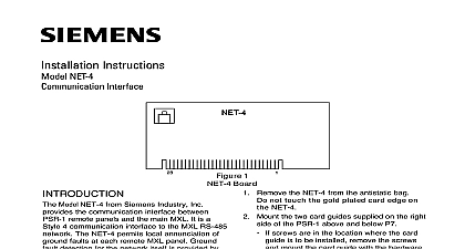
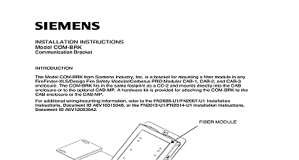
Installation Instructions NET 7M Interface Model NET 7M from Siemens Industry Inc a Style 7 communication interface the main MXL and multiple remote in an MXL system using two separate pairs Each NET 7M except the NET connected to the MMB electrically isolates pairs from the local power supply and iso ground faults to a single remote panel The provides ground fault detection for the two NET 7M connected represents one net drop on the MXL System There can be a of 32 drops green LEDs on the NET 7M indicate the of two communication pairs These light the NET 7M receives a message on a pair Use these two LEDs when trouble to determine if a pair is active NET 7s and NET 4s cannot be in the same system NET 7M does not supervise the network and must be used in combination with the The NET 7M requires CSG M Revision or higher however the NET 7M does not the NET 7 Panel Checking function are two ways to wire a Style 7 network chain and counter rotating The major 1 Board in wiring is where the end of line are located See Figure 2 NET 7M cannot be located at the ends of network pair The end of a pair is defined the point where an end of line resistor is The basic rule is that if either network has an end of line on the screw terminals a must be used Conversely a NET 7M can be used in locations where there are no resistors on the network terminals additional information on the MXL MXLV refer to the MXL MXLV Manual 315 092036 Industry Inc Technologies Division Park NJ 315 094531 7 Building Technologies Ltd Safety Security Products Kenview Boulevard Ontario 5E4 Canada 2 7 Network Wiring Configurations all system power before installation battery and then AC To power up first the AC and then the battery wiring must comply with national local codes Remove the NET 7M from the antistatic bag Do not touch the gold plated edge on the NET 7M Decide whether to install the NET 7M into a or into the enclosure with the MMB If installation is in a PSR 1 skip to step 8 the NET 7M that is in the enclosure the MMB in a MOM 4 slot Any available slot can be used Mount one of the card guides provided in the MOM 4 Slip guide under the mounting screw in the of the MOM 4 and tighten Refer to Figure 2 for the wiring diagram all wiring prior to installing the NET 7M the MOM 4 Failure to properly wire the can cause damage to the board the NET 7M into the MOM 4 slot Be that the board is firmly seated in the card connector This completes the of the NET 7M with the MMB When used with a PSR 1 install the NET 7M connector P7 screws are in the location where the card is to be installed remove the screws mount the card guide with the supplied Mount the two card guides supplied onto PSR 1 by loosening the screws above below P7 Then slide the guides under screws and tighten them Refer to Figure 2 for the wiring diagram the network wires to TB4 on the as shown the NET 7M into P7 Be sure that the is firmly seated RATINGS Industry Inc Technologies Division Park NJ 315 094531 7 Building Technologies Ltd Safety Security Products Kenview Boulevard Ontario 5E4 Canada