Siemens NIM-1W Network Interface Module MXL Wide Area Network Application, Installation Instructions

File Preview
Click below to download for free
Click below to download for free
File Data
| Name | siemens-nim-1w-network-interface-module-mxl-wide-area-network-application-installation-instructions-5327164908.pdf |
|---|---|
| Type | |
| Size | 954.91 KB |
| Downloads |
Text Preview
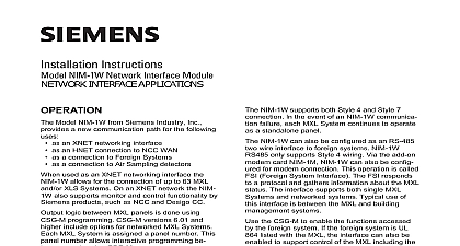
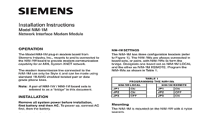
Fire Safety Instructions NIM 1W Network Interface Module use with add on Modem Module WIDE AREA NETWORK APPLICATIONS Model NIM 1W See Figure 1 with SIEMENS NIM 1M See Figure 2 board set provides an System network communications path for an MXL XNET network using a modem the NIM 1W with NIM 1M board set is used to an MXL XNET network up to 63 MXLs can on the network The network can also support Network Command Center NCC that monitors all MXLs in the networked group JUMPER IN ORIENTATION SHOWN POSITION W SELECTED W W D5 7 6 5 4 3 2 1 1 Module Board Building Technologies Inc Fernwood Road Park New Jersey 07932 315 099106 5 logic between MXL panels is accomplished CSG M programming CSG M versions 6.01 higher include options for networked MXL Each MXL system is assigned a panel which allows interactive programming panels using CSG M The NIM 1W 1M set provides a communication link only MXL XNET networks For this reason the board set is not required to be entered the CSG M program 7 6 5 4 3 2 1 JUMPER PLUGS IN AS SHOWN X SHOWN Building Technologies Ltd Kenview Boulevard Ontario L6T 5E4 CN 2 Module Board NIM 1M plug in modem board See Figure 2 to and is connected to the NIM 1W board to modem communication capability See the Installation Instructions P N 315 099105 for and connection to the NIM 1W NIM 1M has 9 status LEDs that indicate the The DTE referred to below is the NIM 1W Request To Send LED ON indicates that DTE Digital Terminal Equipment is ready to data Ring Indicate Not used at this time Carrier Detect LED ON indicates that the has established a connection with a device Receive Data LED FLASHES for receive Transmit Data LED FLASHES for data from the DTE Data Terminal Equip Data Terminal Ready LED ON indicates the DTE Data Terminal Equipment is Data Set Ready LED ON indicates the is ready to operate Clear To Send LED ON indicates to the that it is okay to send data Power LED ON indicates that the modem receiving power MXL XNET network connection to the NIM 1W be either Style 4 or Style 7 The modem trans line connected to the NIM 1M can only be 4 and can be made using standard 18 AWG twisted pair or data grade phone lines A pair of NIM 1W NIM 1M board sets is to as a cid 147 bridge cid 148 in this document all system power before installation battery and then AC To power up connect AC then the battery NIM 1W installs into the MXL optional MOM 4 cage where it occupies one full width slot The can be in either of the full width slots of the The slot determines if the wiring is con to TB3 or TB4 of the MOM 4 The NIM 1M is to the NIM 1W on standoffs the Switches all switches configuration jumpers and cables before installing the NIM 1W board set into the MOM 4 SETTINGS NIM 1M has three configuration headers refer Figure 2 The NIM 1Ms are always connected in sets or pairs with NIM 1Ws to form the Designate one board set as NIM 1M LOCAL the other as NIM 1M REMOTE Program the as shown in Table 1 SETTINGS IN MXL XNET NIM 1W has two configuration dipswitches and two headers Refer to Figure 1 The NIM 1W with the NIM 1M designated as local should be as NIM 1W Local as shown in Table 2 The paired with the NIM 1M designated as remote be configured as NIM 1W Remote as shown in 2 See NOTE below for the operation of cid 1 cid 1 cid 1 cid 1 cid 1 cid 2 cid 2 cid 1 cid 1 cid 1 cid 1 cid 1 cid 2 cid 2 cid 19 cid 25 cid 5 cid 8 cid 19 cid 25 cid 5 cid 8 cid 19 cid 25 cid 5 cid 8 cid 19 cid 25 cid 5 cid 8 4 cid 28 cid 29 cid 29 cid 26 cid 24 cid 29 cid 29 55 open a dipswitch press down on the side of the dipswitch OPEN To close a dipswitch press down on the side of the opposite the side marked OPEN open a slide switch push the slide to the side opposite the side ON To close a slide switch push the slide to the side ON