Siemens OCC-1 Output Control Card, Installation Instructions

File Preview
Click below to download for free
Click below to download for free
File Data
| Name | siemens-occ-1-output-control-card-installation-instructions-5728430619.pdf |
|---|---|
| Type | |
| Size | 739.24 KB |
| Downloads |
Text Preview
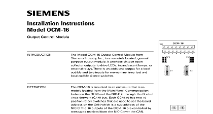
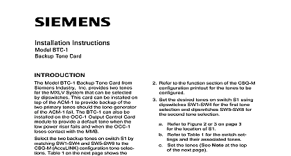
Installation Instructions OCC 1 Control Card Model OCC 1 Output Control Card Siemens Building Technologies Inc an MXLV module that controls Voice cards such as the zone cards plug into the OMM 1 Output Master Commands received from the system through the network bus are by the OCC 1 The commands then sent to the other cards in the for implementation least one OCC 1 is required in each System It supervises and controls to 11 plug in cards each having a subaddress Several types of cards connect to the OCC 1 Up to three audio risers connect to the These signals are available to power amplifiers The BTC 1 Backup Tone card is an module that also plugs into OCC 1 In an installation with amplification the BTC the tone for the degrade of operation then if Network fail and a local alarm detected the tone from BTC 1 is at the Channel A amplifier The telephone riser also connects to OCC 1 The telephone signal is through the OMM 1 telephone bus to any ZCT 8B telephone control cards that are plugged the OMM 1 Building Technologies Inc Fernwood Road Park New Jersey 07932 315 090918 12 Safety OCC 1 supervises the cards under its such as the ZC zone card series each card is supervised by the OCC 1 card responds with its status The information is then sent to the MXL OCC 1 occupies a network address the address on switch S1 When an OCC 1 card use the CSG M configuration printout to locate address of the card Follow the switch instructions in Table 1 to set the address additional information on the Voice refer to the MXL MXLV Manual 315 092036 all system power before first the battery and AC To power up connect the first and then the battery Remove the card from its protective Do not touch the gold edge of the Refer to the CSG M configuration for the address of the module Building Technologies Ltd Kenview Boulevard Ontario L6T 5E4 Canada Set the card address on switch S1 Switch S2 is not presently used but it dipswitches SW1 SW8 be left in place Refer to Figure 1 for the location of Refer to Table 1 for the switch S1 Set the address See NOTE below To open a dipswitch press on the side of the dipswitch OPEN To close a dip press down on the side of dipswitch opposite the side OPEN open a slide switch push slide to the side opposite the marked ON To close a slide push the slide to the side ON There is a jumper E1 on the OCC 1 to Figure 1 for its location If the amplifier is used place E1 in the right hand position connects the backup amplifier negative side to the MXLV power Do NOT install the card in its edge until ALL OMM 1 2 field is completed and checked for opens and other faults Refer Wiring and to the OCC 1 Wiring Chart Replace the card in protective bag if the wiring is not Place the user key from the installa kit in the OMM 1 2 card edge for the OCC 1 See Figure See Figure 3 for the exact location the key for this module This pre installation of any other card in the OCC 1 slot all times handle any plug in with extreme care When in or removing a card be the card is kept at right to the OMM board Other the plug in card can damage displace other components Figure 1 Output Control Card Module Two keys to prevent reverse installa of the card are already factory in the OMM 1 2 edge con See Figure 3 After completing and checking all field place the card in its card edge The components on the must face the 22 position block where the wiring is Press the card firmly in to be sure it is seated properly in edge connector to Figure 4 wiring must comply with and local codes wire size AWG shielded twisted pair wire size AWG shielded twisted pair loop resistance ohms for both wires RATINGS of Line Resistors risers 10K 1 2W 5 140 820396 risers 5.6K 1 2W 5 140 820390 2 the User Key in the OMM Edge Connector of the User Key for the OCC 1 3 wiring must conform to National and Local codes CONNECT AN EOL ONLY IF IS THE LAST OCC 1 CARD POWER LIMITED NOTES 1 AND 2 RISER 1 RISER 1 RISER 1 SHIELD THE NEXT IN THE RISER 1 RISER 1 RISER 1 SHIELD THE TBM PREVIOUS IN THE this OCC 1 is the last or the only OCC 1 terminate the shown as follows risers riser 5 P N 140 820396 5 P N 140 820390 Maximum loop resistance 20 ohms for telephone and audio Minimum wire size wire size AWG twisted pair shielded AWG twisted pair shielded Configure Generic input with CSG M for either NC or NO dry input or normally low or normally high 5 24 VDC input input supervision is enabled in CSG M for any type of failure Wire the NC or NO dry contact input across terminals and 14 Wire the normally low or normally high 5 24 VDC input terminal 14 Normally low high going input high low going input The EL 410C D power supervision is normally low input Refer to Wiring Specification for MXL MXL IQ and MXLV P N 315 092772 revision 6 or higher for additional information Positive and negative ground fault detected at 70K ohms terminals 17 22 2 3 TERMINAL 8 NOTE 4 USE WITH PL864 25S ONLY THE ONLY AT EL 410C D CHANNEL A AMPLIFIER 1 INPUT CHANNEL A AMPLIFIER 1 INPUT CHANNEL B AMPLIFIER 2 INPUT CHANNEL B AMPLIFIER 2 INPUT CHANNEL C AMPLIFIER 3 INPUT CHANNEL C AMPLIFIER 3 INPUT POWER LIMITED AMPLIFIER INPUT AND OUTPUT CABLES SEPERATE CONDUITS 4 Riser Connections WIRING CHECKOUT CHART Cause of shorted open EOL EOL shorted open EOL EOL to 11 to chassis 1 Meg in wiring 1 Meg in wiring 1 Meg shorted 1 Meg in wiring to 2 to 5 to 8 to 3 to 4 to 6 to 7 to 9 to 10 to 12 to 13 to 18 to 20 to 22 to 17 to 19 to 21