Siemens OCM-16 Cerberus PRO Modular Output Control Module, Data Sheet

File Preview
Click below to download for free
Click below to download for free
File Data
| Name | siemens-ocm-16-cerberus-pro-modular-output-control-module-data-sheet-1257638904.pdf |
|---|---|
| Type | |
| Size | 950.68 KB |
| Downloads |
Text Preview
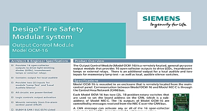
PRO system Control Module OCM 16 Architect Engineer Specifications Product Overview Provides 16 open collector to drive light emitting LEDs incandescent or external relays Contains output for local audible Provides two 2 inputs for Test and Silence All circuits are power limited Logic controls output activation Mounts remotely from fire alarm panel FACP UL864 CAN ULC S576 Listed CSFM NYC Fire Department Output Control Module Model OCM 16 is a remotely located general purpose module that provides 16 open collector outputs to drive LEDs incandescent or external relays There is an additional output for a local audible and two for momentary lamp test as well as local audible silence switches Specifications OCM 16 is mounted in an enclosure that is remotely located from the main panel Communication between Model OCM 16 and Model NIC C is through Control Area Network CAN bus Model OCM 16 has two 2 10 position rotary switches that used to set the board address on the CAN which is a sub of Model NIC C The 16 outputs of Model OCM 16 are by messages received from the NIC C over the CAN bus CAN message can activate any or all of the 16 open collector to drive LEDs incandescent 24 volt lamps or relays the any of the outputs are activated LEDs lamps or relays will sound until If the outputs are de activated before the alarm is the alarm will silence audible if lamp test and audible silence switch on multiple Model OCM modules can be connected to a single switch one for each A single audible can also be used with multiple Model modules OCM 16 may be installed in a REMBOX2 REMBOX4 or in any UL 864 9th Edition Listed enclosure If using REMBOX2 or mount Model OCM 16 one 1 space on the or REMBOX4 MP to four 4 Model OCM 16 modules will mount in REMBOX2 to eight 8 Model OCM 16 modules will mount in REMBOX4 OCM 16 fits in a single System 3 module footprint OCM 16 Control Technologies Division Sheet 8318 Temperature and Humidity Range are UL 864 9th Edition Listed for indoor dry locations within a temperature range of 120 3 49 2 32 3 0 2 and a relative humidity of 93 2 at a temperature of 90 3 32 2 Ratings POWER CURRENT DRAW Plane CURRENT DRAW Terminal CURRENT DRAW Plane CURRENT DRAW max 10mA active LED max 10mA active LED POWER NETWORK PAIR peak to peak max max message transmission for Ordering TYPE CABLE Ft 0.91 cm Required 500 033150 Output Control Lobby 500 633772 500 633914 Medium Lobby NOTICE The information contained in this data sheet document is intended only a summary and is subject to change without notice product s described here has have a specific instruction sheet s cover various technical limitation and liability information of install type instruction sheets as well as the General Product and Limitations document which also contains important data provided with the product and are available from the Manufacturer contained in the aforesaid type of documentation should be consulted a fire safety professional before specifying or using the product further questions or assistance concerning problems that might arise relative to the functioning of the equipment please contact Manufacturer PRO Industry Inc Technologies Division Fernwood Road Florham Park NJ 07932 973 593 2600 2017 New Issue 0