Siemens OCM-16RC Output Control Module Ribbon Cable, Installation Instructions

File Preview
Click below to download for free
Click below to download for free
File Data
| Name | siemens-ocm-16rc-output-control-module-ribbon-cable-installation-instructions-1826475903.pdf |
|---|---|
| Type | |
| Size | 655.54 KB |
| Downloads |
Text Preview
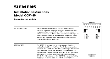
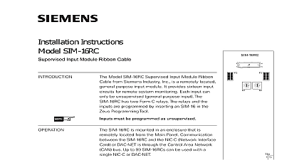
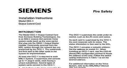
Installation Instructions OCM 16RC Control Module Ribbon Cable 5 6 5 6 1 Output Module Ribbon Model OCM 16RC Output Control Module Ribbon from Siemens Industry Inc is a remotely located purpose output module It provides sixteen collector outputs to drive LEDs incandescent or external relays There is an additional output a local audible and two inputs for momentary lamp and local audible silence switches The outputs are by inserting the OCM 16 in the Zeus Tool OCM 16RC is mounted in an enclosure that is located from the Main Panel Communication the OCM and the NIC C or DAC NET is the Control Area Network CAN bus Each has two 10 position rotary switches that are to set the board address on the CAN which is a of the NIC C or DAC NET The 16 outputs of OCM 16RC are controlled by messages received the NIC C or DAC NET over the CAN CAN message can activate any or all of the 16 outputs drive LEDs incandescent 24 Volt lamps or relays any of the outputs is activated LEDs lamps relays ON the local audible if installed will sound it is acknowledged by shorting position 19 and 20 TB2 If the outputs are deactivated before the alarm audible is acknowledged the alarm local audible cease to sound shorting terminals 17 and 18 all LEDs or lamps will on to confirm that they are working and automatically return to their normal state after a few seconds Both lamp test and local audible silence switch on multiple can be connected to a single switch one for function A single audible can also be used with OCM 16RCs 315 050716 1 Inc Inc Inc Industry Inc Inc TTTTTececececechnologies Di Di Di Division Di Address Switches Set the board address for each OCM 16RC using both of ten position rotary switches located on the board See Figure 2 Each of these must be a sub address of the NIC C or DAC NET and must be the same the addresses assigned in the Zeus Programming Tool LED Incandescent Relay Select Switches When the external Graphics Panel to interface does not provide their own limiting resistors open corresponding dipswitches on S1 and S2 to OCM 16RC Switches Table to provide a current limiting resistor of ohms to each LED the External Graphic Panel such as Geographics GEO LS8 75 GEO LS8 1 current limiting resistors when incandescent lamps or relays are close corresponding dipswitches on S1 and S2 Refer to OCM 16RC Table to bypass the limiting resistors OCM 16RC may be installed in a REMBOX When using REMBOX 2 or 4 mount OCM 16RC in one module space on a REMBOX2 MP P N 500 634211 or P N 500 634212 using the four screws provided Refer to REMBOX2 Installation Instructions P N 315 034211 Up to 4 OCM 16RCs fit in a REMBOX2 up to 8 OCM 16RCs will fit in a REMBOX4 all system power before installation first battery then AC To power up the AC first then the battery OCM 16RC module is a node in the CAN bus OCM 16RC can be installed with or without an RNI Connect 24V and bus as shown in Figures 2 and 3 to 99 CAN modules in any combination can be connected to the CAN of each NIC C or DAC NET OCM 16RC module is shipped with one CCS cable Industry Inc Technologies Division 315 050716 1 connections for OCM 16RC modules are shown in the following CAN bus requires a 120S resistance at each end of the loop Refer to the NIC C Instructions P N 315 033240 for details about CAN termination NO CONNECT RELAY 24V TERMINATOR 110 134215 WITH NIC C ON BE SET TO FOR LEDs 5 6 5 6 SWITCHES 5 6 5 6 V V RET V V RET NOT USE NOT USE PSC 12 PSX 12 TB3 ANY REGULATED LIMITED POWER LISTED FOR PROTECTIVE USE PSC 12 TB1 NIC C 315 033240 WIRING DETAILS TEST ALARM OPEN MOMENTARY PUSHBUTTON UL 864 LISTED AUDIBLE 50mA MAX UL 864 LISTED NEXT 2 Wiring Without An RNI All wiring must be in with Article 760 NEC or local building All circuits are power limited article 760 of NEC Electrical Ratings current 14mA max 24VDC current 200mA 24VDC For additonal information to the NIC C Installa Instructions P N 315 The Ribbon Cables for JP1 JP2 must be within the same room within 20 feet in rigid conduit Lamp test switch ACK switch and audible must be UL 864 devices CAN network max line 15S Mount the Lamp Test Ack and Audible Device on REMBOX2 4 front door Wiring for TB2 is 18 AWG 12 AWG max Wiring for TB3 is 18 AWG 16 AWG max Refer to PSC 12 Installation P N 315 for ground fault impedances Industry Inc Technologies Division 315 050716 1 CCS RNI P4 TERMINATOR 110 134215 WITH NIC C CCL 5 6 5 6 5 6 5 6 5 6 5 6 5 6 5 6 3 CAN Bus Connections With An RNI ribbon cable for JP1 and JP2 is to be provided with the External Graphics Panel RATINGS Industry Inc Technologies Division Park NJ Canada Limited Technologies Division Kenview Boulevard Ontario L6T 5E4 Canada 315 050716 1