Siemens OH921 Multi-Criteria Smoke Detector, Installation Instructions

File Preview
Click below to download for free
Click below to download for free
File Data
| Name | siemens-oh921-multi-criteria-smoke-detector-installation-instructions-4897625310.pdf |
|---|---|
| Type | |
| Size | 739.65 KB |
| Downloads |
Text Preview
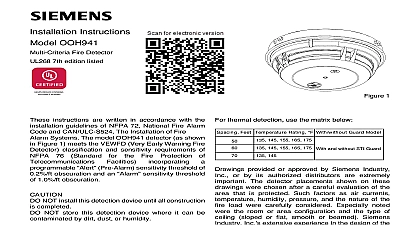
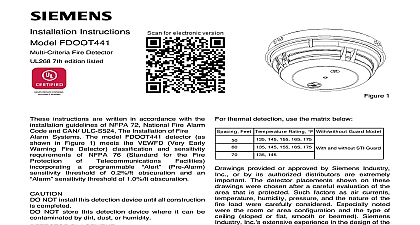
Installation Instructions OH921 Smoke Detector 7th edition listed 1 instructions are written in accordance with the guidelines of NFPA 72 National Fire Alarm and CAN ULC S524 The Installation of Fire Alarm NOT install this detection device until all construction completed NOT store this detection device where it can be by dirt dust or humidity PLACEMENT no specific spacings are set for the detectors for a clean air application use 30 foot center 900 sq ft from NFPA Standard 72 initiating chapter and CAN ULC S524 if practical as a or starting point for a detector installation layout spacing however is based on ideal conditions ceiling no air movement and no physical less area is protected adequately by each detector This is why it is mandatory to closely the installation drawings In all installations place detector on the ceiling a minimum of 6 inches from side wall or on a wall 12 inches from the ceiling the detector is used as heat only locate it on the at least 4 inches from the side walls For an smooth ceiling condition place the detectors at a center spacing of 50 feet 2500 square Drawings provided or approved by Siemens Inc or by its authorized distributors are important The detector placements shown on drawings were chosen after a careful evaluation of area that is protected Such factors as air currents humidity pressure and the nature of the load were carefully considered Especially noted the room or area configuration and the type of sloped or flat smooth or beamed Siemens Inc extensive experience in the design of the assures the best detector placement by following drawings Sound engineering by personnel must be followed AVOID NUISANCE ALARMS not locate the detectors where excessive smoke exist under normal conditions or in areas prolonged high relative humidity where condensation not locate the detectors next to an oil burner or where exhaust fumes can trigger an alarm Other of false alarms are dust accumulation heavy of steam heavy pipe or cigar smoke and aerosol sprays CURRENTS a detector can sense a fire the products of or smoke must travel from the fire to the This travel is especially influenced by air consider air movement when the system While combustion products tend rise drafts from hallways air diffusers fans etc may or hinder the travel of combustion products to the When positioning a detector at a particular give consideration to windows and doors both and closed to ventilating systems both in and out operation and to other influencing air Do not install a detector in the air stream of room air supply diffuser It is better to position a closer to an air return distance that products of combustion or smoke from a fire to the detector is not usually the shortest route Combustion products or smoke usually rise the ceiling then spread out Average ceiling heights of to 10 feet do not abnormally affect detector response ceilings churches warehouses etc do affect detector response and should considered CEILING CONSTRUCTION FACTORS obstructions change the natural movement of air combustion products Depending on the direction of travel joists and beams can slow the movement heated air and smoke while pockets between them contain a reduced level of smoke Take obstructions by girders joists beams air conditioning ducts architectural design consideration when area protection Refer to the Initiating chapter of NFPA Standard 72 for Location and requirements for specific types of construction beam suspended level sloped and peaked The detector is also compatible with the mechanical protection guard model STI 9604 www STI USA com for details Industry Inc Infrastructure HUMIDITY PRESSURE AIR temperature range for the OH921 detector is 32 to 100 38 Use the detector in environments the humidity does not exceed 95 non Normal changes of atmospheric pressure not affect detector sensitivity The air velocity range is ft min for open areas applications and 0 4000 for direct in air duct applications Follow detector and location requirements in NFPA 72 Chapter High Air Movement Areas and Control of Smoke INDICATOR OPERATION Model OH921 contains an LED indicator capable of either one of three distinct colors green yellow red The microprocessor based detector monitors the Smoke in its sensing chamber Smoke sensitivity is within the range indicated on the label sensors and electronics on the results of the monitoring the LED indicator the following Interval supervisory operation sensitivity is within rated is in trouble and needs is not powered or is needed LED can be turned off Please follow the corresponding of the Panel used PROGRAMMING detector must be programmed to respond to an between 001 252 program the detector address use the Model DPU Programming Unit Refer to the DPU Manual P N the loop and device number system address for detector on the detector label and on the base to installing the detector in the wrong base The DPU label printer can be used for this purpose detector provides pre programmed parameter sets can be selected by the panel OH921 provides two alarm sources which can be selected and on or off individually by the panel Follow the description of the panel used source 1 Combined smoke heat Standard Duct When a OH921 with product version is the parameter setting Robust is changed Duct which shall only be used in Duct When using detector direct air duct be sure the detector is set to the source 2 Heat only Fixed 135 57 Rate of rise detection 15 8.3 at fixed 57 OH921 supports two operation modes polarity mode and isolator mode The Detector can be for either mode refer to Figure 2 and 3 During isolator mode the built in dual isolators will work at sides of the Detector to isolate the line short in front behind the device the OH921 is wired in polarity insensitive mode 6 and 5 can be either line of the loop the OH921 is wired for Isolator mode the positive needs to be connected to 1b and the negative line to The next device needs to be connected to 1b and 5 Line Isolator is located between connector 6 and 5 that the panel supports Isolator mode for OH921 product version 17 mode must not be used with a OH921 version 17 You will find the product number on the detector label 17 MOUNTING ensure proper installation of the detector head into the be sure the wires are properly dressed at Position all wires flat against the base Take up all slack in the outlet box Route wires away from connector terminals INSTALL DETECTOR HEAD Rotate detector counterclockwise while gently on it until the detector seats fully into base rotate the detector clockwise until it stops and in place Insert optional locking screw Order LK 11 REMOVE DETECTOR HEAD locking screw if installed Then rotate the counterclockwise until stop is reached Pull detector out of base TESTING qualified service personnel should test To assure operation of the detector both the Sensitivity and Test should be conducted The minimum test may be found in the current edition of NFPA 72 MEASUREMENT sensitivity of OH921 detectors can be tested using the DPU Refer to the DPU Manual 315 033260 The sensitivity can be measured by the Follow the instructions of the panel used