Siemens PAD-4-CLSA NAC Extender Board, Installation Instructions

File Preview
Click below to download for free
Click below to download for free
File Data
| Name | siemens-pad-4-clsa-nac-extender-board-installation-instructions-3586724091.pdf |
|---|---|
| Type | |
| Size | 640.41 KB |
| Downloads |
Text Preview
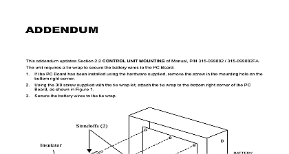
Installation Instructions PAD 4 CLSA NAC Extender Board PAD 4 CLSA Module for the PAD 4 Distributed Module provides two Class A Style Z notifica appliance circuits This module is optional for UL but is required for ULC installations set for ULC operation the normally open Form Contact at TB3 provides ground fault detection to the control panel One PAD 4 CLSA may be mounted on the PAD 4 main board 1 1 Module SUPPLIED Module Male Female Standoffs Header x 1 4 Screws Terminal Blocks PRE INSTALLATION the jumper placed on J2 of PAD 4 MB to configure the module for UL Then set the programming jumpers and switch S1 for Class A operation to the PAD 4 Installation Operation and Maintenance Manual P N 315 050217 more information See Figure 2 5 of the PAD 4 Manual for the location of J2 PRE INSTALLATION the programming jumpers and switch S1 of PAD 4 MB for Class A or Class B Refer to the PAD 4 Installation Operation and Maintenance Manual P N for more information is to be done by qualified personnel who have thoroughly read and this instruction sheet all system power before installation first battery then AC To power up the AC first then the battery mount the PAD 4 CLSA Module on the PAD 4 MB follow the steps listed below to Figure 2 the header into P1 the 12 position receptacle on the PAD 4 MB the two standoffs into the two holes on the PAD 4 MB that are below P1 the header placed on the PAD 4 MB with the 12 position receptacle the underside of the PAD 4 CLSA Refer to Figure 3 the 2 holes on the PAD 4 CLSA module over the two standoffs that inserted in the PAD 4 MB the PAD 4 CLSA module to the standoffs with the two 4 40 x 1 4 provided Inc Inc Inc Industry Inc Inc TTTTTececececechnologies Di Di Di Division Di 315 050254 1 for header 2 the PAD 4 CLSA Module 3 Underside in accordance with the local code and Article 760 of the NEC NFPA 70 latest and Canadian Electrical Code C22.1 Part 1 Refer to Figure 4 Connect External Wiring Tighten the screw of the terminal block by turning it clockwise the screw of the terminal by turning it counterclockwise the wire into the side of the terminal block 1 4W 140 830185 OHMS 1 4W 140 820164 APPLICABLE EARTH Z APPLIANCE CIRCUIT A POWER LIMITED P N 315 096363 OR P N 315 096363FA APPLICABLE FOR COMPATIBLE DEVICES SHOWN IN ACTIVATED CONDITION 4 the PAD 4 CLSA Module Terminal blocks will accept Units to be installed in with all local codes maximum of 12 AWG minimum of 18 wiring Refer to the PAD 4 P N 315 050217 ground fault impedance RATINGS Voltage Range Special Application 16 32 VDC to Siemens Compatible Notification Appliances P N 315 096363 or Faraday Compatible Notification Appliances P N 315 096363FA as for maximum number per NAC appliances permitted Class A Style Z circuits limited Maximum Alarm Current 3.0A per circuit Maximum Standby Current 1.0mA Maximum Ripple 100mVAC Maximum Line Resistance 3.0 ohms 3.0 amps ohms 2.5 amps ohms 2.0 amps ohms 1.5 amps TB3 Ratings Fault Industry Inc Technologies Division Park NJ Canada Limited Technologies Division Kenview Boulevard Ontario L6T 5E4 Canada 315 050254 1 ID A6V10405805