Siemens PAL-1 Parallel Printer, Installation Instructions
File Preview
Click below to download for free
Click below to download for free
File Data
| Name | siemens-pal-1-parallel-printer-installation-instructions-7265043819.pdf |
|---|---|
| Type | |
| Size | 670.99 KB |
| Downloads |
Text Preview
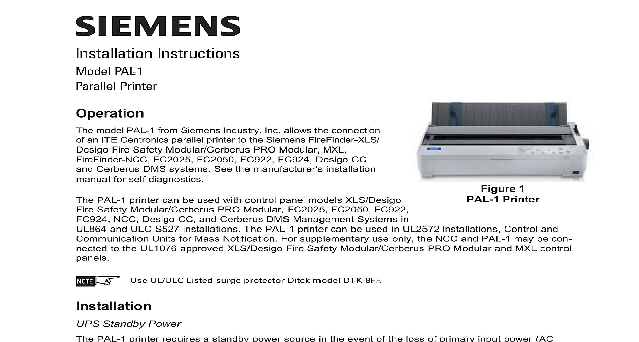
Installation Instructions PAL 1 Printer model PAL 1 from Siemens Industry Inc allows the connection an ITE Centronics parallel printer to the Siemens FireFinder XLS Fire Safety Modular Cerberus PRO Modular MXL FC2025 FC2050 FC922 FC924 Desigo CC Cerberus DMS systems See the manufacturer s installation for self diagnostics PAL 1 printer can be used with control panel models XLS Desigo Safety Modular Cerberus PRO Modular FC2025 FC2050 FC922 NCC Desigo CC and Cerberus DMS Management Systems in and ULC S527 installations The PAL 1 printer can be used in UL2572 installations Control and Units for Mass Notification For supplementary use only the NCC and PAL 1 may be con to the UL1076 approved XLS Desigo Fire Safety Modular Cerberus PRO Modular and MXL control Printer 1 Use UL ULC Listed surge protector Ditek model DTK 8FF Standby Power PAL 1 printer requires a standby power source in the event of the loss of primary input power AC Refer to Figure 2 for the connection of a UPS to meet this requirement TRI 60 B6 S OR HTRI S D R INPUT PROGRAM AS NORMALLY OPEN CAUSING INPUT IN CSG M AccuLINK ZEUS AND FPI 32 OR DPU AS APPLICABLE TO TRI 60 INSTALLATION INSTRUCTIONS 315 092329 THE TRI B6 INSTALLATION P N 315 093315 THE TRI S INSTRUCTIONS P N 315 096242 OR THE HTRI S D R INSTALLATION P N 315 033300 OR 315 049075 APPLICABLE BLOCK ON SYSTEM BOARD VAC NOT TO VAC NOTE 4 NOT VAC INPUT VAC FILTER VAC OF UPS 2 Wiring Diagram 1 All wires 14 AWG min 600V insulation 2 Wiring to the printer and must be 14 AWG min 600V insulation in conduit and located in the same room as the panel 3 Use the UPS ICS Lifeline Model 9300057 4 Standby Power requirements 120 VAC 3A for 24 hours 315 092408 AT Inc Inc Inc Industry Inc Inc Infrastruct Infrastruct Infrastructureureureureure Infrastruct Infrastruct Fire Safety Modular Cerberus PRO Modular System The FireFinder XLS Desigo Fire Safety Modular Cerberus PRO Modular system requires a Siemens model module to interface to a Centronics parallel printer When an RPM is used in conjunction with PAL 1 FireFinder XLS Desigo Fire Safety Modular Cerberus PRO Modular system provides a supervised printer meeting the requirements of an NFPA 72 Proprietary or UL1076 Security system The printer supervised for paper out AC loss and printer parallel cable removal Refer to the RPM Installation Instructions P N 315 033270 for more details on connecting and a RPM module Figure 3 shows the proper installation of PAL 1 with an RPM module Fire Safety Modular Cerberus PRO Modular System 3 maximum distance from the RPM to the PAL 1 is 6 feet The two modules must be in the same room Wiring to printer must be 14 AWG min 600V insulation in conduit and located in the same room as the control panel NFPA 72 Local Auxiliary and Remote Station configurations connect the output of the RPM to any ITE listed printer printer must support the EPSON FX command set printer is supervised for paper out AC loss and printer parallel cable removal by the RPM the Panasonic printer After loading the paper in the PAL 1 printer turn off the power and follow the steps below While pressing the LOAD PARK button turn on the power to the PAL 1 printer Keep pressing the PARK button for 5 seconds Release the LOAD PARK button When printing is completed the ON LINE indicator will be lit If the ON LINE indicator is not lit press the ON current setting will print button the Epson LQ2090 and LQ2090ii printers Follow the steps below to enter default setting mode If single paper is loaded you ll need to load a new sheet each time the printer ejects a printed page For Auto line feed the default setting must be On as described in Step e Make sure the printer is on and paper is loaded Then press the Menu buttons Item cid 207 and Set until the beeps and both the Menu lights turn on printer enters default setting mode and prints a line showing which language is currently selected for the instructions If the printer does not access default setting mode the printer is in lock out mode When the lock out mode on the Pause and Paper Out lights flash simultaneously when the locked buttons are pushed Follow the for turning off the lock out mode on page 3 you want a different language press the Item cid 208 button until the printout shows the language you want Press the Set button to accept the language The printer prints a line asking if you want to print all the settings To print a list of all the current settings press the Set button The printer prints all the settings and then the setting again go through the settings one at a time press the Item cid 208 or Item cid 207 button The printer prints the first and its current value Press the Set button to scroll through the options until you see Auto line feed Press the Item cid 208 or Item cid 207 to select On the Set button to scroll through the remaining options for the selected setting until you see the one want Press the Item cid 208 or Item cid 207 button to select the next or previous setting you want to change Repeat Step f for any other settings you want to change When you finish press the Menu buttons Item cid 207 and Set again to exit default setting mode new settings become the printer s defaults Off the Lock Out Mode You can turn off the lock out mode easily by using buttons on the control panel the steps below to turn off the lock out mode Make sure the printer is turned off Whenever you turn off the printer wait at least 5 seconds before turning it back on otherwise you may the printer Press and hold both the Load Eject and Pause buttons While these buttons are pressed turn the printer and the printer will beep once indicating that the default setting menu is unlocked turn on the lock out mode repeat steps a and b The printer beeps twice indicating that the lock out mode has turned on System of the PAL 1 in an MXL system requires that a Siemens model ANN 2 or ANN 3 is installed in system The ANN 2 and ANN 3 come installed in an MKB 5 or MKB 6 respectively An ANN 3 is also in model RCC 3 Refer to the MKB 5 5C Installation Instructions P N 315 048727 the MKB 6 6C Installation Instructions P N and the RCC 3 3R 3C 3FC 3FR Installation Instructions P N 315 048665 for more details on and programming MKB 5 MKB 6 and RCC 3 modules respectively to a PAL 1 printer Figure 4 shows the proper installation of a PAL 1 with an MXL system PRINTER VIEW VAC Hz SUPPLIED PAL 1 SUPERVISED 4 System computer Connect the PAL 1 printer to parallel port on the side of ANN 2 or ANN 3 PAL 1 printer is supervised for paper out AC loss and printer parallel cable removal by the CSG M software at Supervision for the MKB 5 5C and MKB 6 6C printer is set in CSG M In the Network Module Map select the and press Enter Scroll down to Printer Option and press Enter to toggle to the correct printer The fields Operation and Serial Port must both be set to YES All cables must be in rigid conduit and cannot leave the room All circuits except AC Input are power limited FC2050 FC922 or FC924 of the PAL 1 in a FC2025 FC2050 FC922 or FC924 system requires that an FCA2018 U1 is installed Refer to the FCA2018 U1 Installation Instructions P N A6V10315044 for more details on connecting and an FCA2018 U1 to a PAL 1 Figure 5 shows the proper installation of a PAL 1 with a FC2025 FC2050 FC922 or FC924 system FC2050 FC922 5 FC924 The maximum distance from the FCA2018 U1 to the PAL 1 is 6 feet The two modules must be in the same room to the printer must be 14 AWG min 600V insulation in conduit and located in the same room as the panel For NFPA 72 Local Auxiliary and Remote Station configurations connect the output of the FCA2018 U1 to any UL ITE The printer must support the EPSON FX command set For NFPA 72 Proprietary of UL 1076 configurations use printer Siemens Model PAL 1 a UL listed for fire Centronics printer printer The