Siemens PMI PMI-INTL Person-Machine Interface, Installation Instructions
File Preview
Click below to download for free
Click below to download for free
File Data
| Name | siemens-pmi-pmi-intl-person-machine-interface-installation-instructions-1520376948.pdf |
|---|---|
| Type | |
| Size | 893.08 KB |
| Downloads |
Text Preview
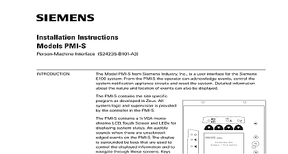
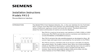
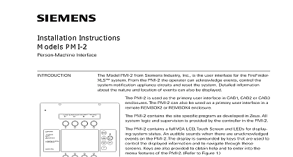
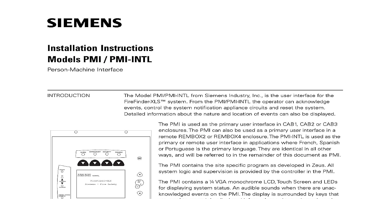
Installation Instructions PMI PMI INTL Interface Model PMI PMI INTL from Siemens Industry Inc is the user interface for the system From the PMI PMI INTL the operator can acknowledge control the system notification appliance circuits and reset the system information about the nature and location of events can also be displayed 04 15 01 STATUS NORMAL Fire Safety SYSTEM PMI is used as the primary user interface in CAB1 CAB2 or CAB3 The PMI can also be used as a primary user interface in a REMBOX2 or REMBOX4 enclosure The PMI INTL is used as the or remote user interface in applications where French Spanish Portuguese is the primary language They are identical in all other and will be referred to in the remainder of this document as PMI PMI contains the site specific program as developed in Zeus All logic and supervision is provided by the controller in the PMI PMI contains a VGA monochrome LCD Touch Screen and LEDs displaying system status An audible sounds when there are unac events on the PMI The display is surrounded by keys that used to control the displayed information and to navigate through screens Keys are also provided to obtain help and to enter into menu features of the PMI Refer to Figure 1 the back of the PMI there are additional diagnostic displays to aid in troubleshooting This is also where the PMI address is set and the connection is made to Zeus for programming Refer to 2 contrast pot is provided on the back of the PMI to adjust the LCD for best visibility 1 User Interface systems configured to provide Smoke Controk UUKL refer to the XLS Control Panel System Manual P N 315 034853 PMI INTL comes with French Canadian labels applied to the PMI Labels in additional languages are also shipped with the PMI INTL To apply the labels for alternate language first remove the French Canadian labels Then select the label English Spanish or Portuguese Brazilian from the Power kit P N 575 434249 and the Alarm label kit P N 575 434218 Remove the from the labels and apply them to the PMI Refer to Figure 3 Discard the labels 315 033070 6 Industry Inc Technologies Division 0 0 0 DEBUG 9 2 Diagnostics APPROPRIATE 575 434218 HERE 575 434249 HERE 04 15 01 STATUS NORMAL Fire Safety SYSTEM 3 PMI INTL Labels Industry Inc Technologies Division 315 033070 6 DOOR ELECTRICAL POWER prior to installing the PMI PMI INTL in the enclosure the PMI from its anti static bag Set the three digit network address using the rotary switches located on the back of the PMI For HNET set the PMI to 253 Make sure that the PMI is configured at this address in the Zeus view the PMI is used with XNET the three digit network address switch is used to the XNET node address In order to configure the PMI for XNET operation first set 4 of the options switch S17 to ON Refer to Figure 2 for the location of the switch Next set the XNET node address that has assigned in Zeus on the address switches Be sure to set all leading zeros For example Node 2 is at 002 The MNET address of the PMI is automatically set to 253 when position 4 S17 is in the ON position the location of the contrast pot Although the PMI comes from the factory with LCD contrast adjusted this adjustment may not be proper for the viewing angle the LCD once it is installed in the enclosure If the contrast appears poor with the powered open the inner door and locate the contrast pot on the lower edge the PMI printed circuit board Adjust this pot until the LCD contrast is acceptable PMI PMI INTL mounts to the rear of the inner door in the CAB 2 CAB 3 REMBOX2 or REMBOX4 enclosures the location of the PMI It can be mounted either in the or on the left side of the inner door when viewed from outside of the enclosure Place the PMI onto the inner from the rear over the four mounting studs in the desired Secure the PMI to the inner door with the four nuts Refer to Figure 4 40 inch long 60 wire cable P N 555 133743 connects the to the CC 5 The CC 5 is located in the back of enclosure on the left hand side Connect one end of the to JP3 on the PMI JP3 is marked with on the printed circuit board Connect the other end of cable to P1 on the CC 5 Refer to Figure 5 the PMI to the RNI in a REMBOX2 4 The RNI is in the back of the enclosure on the top left hand side one end of the cable to JP3 on the PMI PMI INTL is marked with on the printed circuit board the other end of the cable to JP1 on the RNI Refer Figure 6 4 The PMI PMI INTL The Rear Of The Inner Door sure that all cables snap fully into their connectors and close the locking levers the top of each cable connector Secure the cable in the back box using cable and the tie down points in the enclosure The cable must have sufficient slack to the inner door to open fully without putting stress on the cable Industry Inc Technologies Division 315 033070 6 5 The PMI PMI INTL To The CC 5 6 The PMI PMI INTL To The RNI the normal standby condition the PMI displays the site specific custom message time and date and a synopsis of the system status an event occurs in the system the display enters the Alert mode The event is the local audible sounds and the appropriate LED blinks If the event notification appliances to sound the Audibles On indicator lights At the of the screen an acknowledge button is displayed Pressing this button the event and silences the local audible Once all events are acknowl a reset button becomes available in the lower right side of the display If appliances were active two additional buttons appear at the bottom of screen These allow the operator to silence or unsilence the notification appli When the notification appliances are silenced the Audibles Silenced LED The system can only be reset with the notification appliances silenced more events are present in the system than can be displayed on a single screen a bar appears to the right of the event list Pressing the up and down navigation to the right of the LCD allows the operator to move through the list The event is highlighted in the display Pressing the More Info button will display screen showing details relating to the selected event Other buttons also appear at bottom of this screen There is an expanded text message available and a selec to show all of the devices associated with the event that are active The operator return to the previous screen by pressing the ESC button which is adjacent to More Info button For more detail on PMI operation refer to the FireFinder XLS P N 315 033744 RATINGS