Siemens PMI-S Person-Machine Interface, Installation Instructions
File Preview
Click below to download for free
Click below to download for free
File Data
| Name | siemens-pmi-s-person-machine-interface-installation-instructions-3450167289.pdf |
|---|---|
| Type | |
| Size | 861.32 KB |
| Downloads |
Text Preview
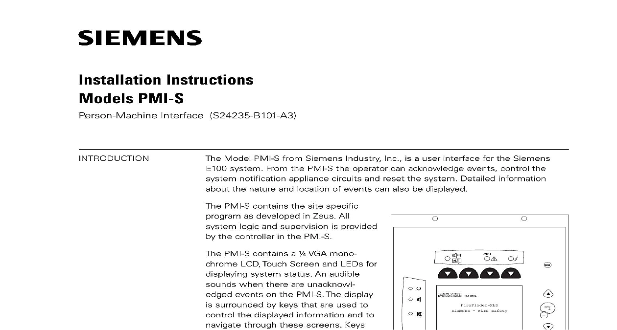
Installation Instructions PMI S Interface S24235 B101 A3 Model PMI S from Siemens Industry Inc is a user interface for the Siemens system From the PMI S the operator can acknowledge events control the notification appliance circuits and reset the system Detailed information the nature and location of events can also be displayed PMI S contains the site specific as developed in Zeus All logic and supervision is provided the controller in the PMI S PMI S contains a VGA mono LCD Touch Screen and LEDs for system status An audible when there are unacknowl events on the PMI S The display surrounded by keys that are used to the displayed information and to through these screens Keys also provided to obtain help and to into the menu features of the Refer to Figure 1 the back of the PMI S there are diagnostic displays to aid in troubleshooting This is also the PMI S address is set and the connection is made to Zeus programming Refer to Figure 2 contrast pot is provided on the back the PMI S to adjust the LCD for the visibility 04 15 01 STATUS NORMAL Fire Safety 1 User Interface 315 035860 3 Edition 3 Industry Inc Technologies Division 0 0 0 DEBUG 9 ELECTRICAL POWER prior to installing the PMI S in the enclosure the PMI S from its anti static bag Set the three digit network address using 10 position rotary switches located on the back of the PMI S Set the PMI S to Make sure that the PMI is configured at this address in the Zeus physical view the location of the contrast pot Although the PMI S comes from the factory the LCD contrast adjusted this adjustment may not be proper for the viewing of the LCD once it is installed in the enclosure If the contrast appears poor the system powered open the inner door and locate the contrast pot on the edge of the PMI S printed circuit board Adjust this pot until the LCD contrast acceptable 2 Diagnostics Industry Inc Technologies Division 315 035860 3 Edition 3 PMI S mounts to the rear of the inner door in the enclosure Select the location the PMI S It can be mounted either in the center or on the left side of the inner when viewed from the outside of the enclosure Place the PMI S onto the inner from the rear over the four mounting studs in the desired location Secure the to the inner door with the four nuts provided Refer to Figure 3 73 inch long 60 wire cable connects the PMI S to the CC 5 The CC 5 is located in back of the enclosure on the left hand side Connect one end of the cable to JP3 the PMI S JP3 is marked with on the PMI S printed circuit board Connect other end of the cable to P1 on the CC 5 Refer to Figure 4 sure that all cables snap fully into their connectors and close the locking levers the top of each cable connector Secure the cable in the back box using cable and the tie down points in the enclosure The cable must have sufficient slack to the inner door to open fully without putting stress on the cable DOOR 3 The PMI S To The Rear Of The Inner Door 4 The PMI S To The CC 5 Industry Inc Technologies Division 315 035860 3 Edition 3 the normal standby condition the PMI S displays the site specific custom message time and date and a synopsis of the system status The the CPU is not working properly or the system is resetting CPU LED will light an alarm occurs in the system the display enters the Alarm mode The event displayed the local audible sounds and the appropriate LED blinks If the event notification appliances to sound the the lower right side of the display If notification appliances were active two buttons appear at the bottom of the screen These allow the operator to or unsilence the notification appliances When the notification appliances are the silenced LED lights The system can only be reset with the notification LED lights A reset button is available more events are present in the system than can be displayed on a single screen a bar appears to the right of the event list Pressing the up and down navigation to the right of the LCD allows the operator to move through the list The event is highlighted in the display Pressing the INFO button will display a showing details relating to the selected event Other buttons also appear at bottom of this screen There is an expanded text message available and a to show all of the devices associated with the event that are active The can return to the previous screen by pressing the ESC button which is to the INFO button For more details on PMI operation refer to the Instructions Siemens E100 Order No A24205 A334 B845 English or Siemens E100 Best Nr A24205 A334 A845 German RATINGS CE applications in Siemens E100 systems refer to Instruction A24205 A334 B844 English or A24205 A334 A844 German Siemens AG I BT FS SYS 2003 2011 Industry Inc Florham Park NJ Canada Limited Brampton Ontario L6T 5E4 Canada by Siemens AG BT FS SYS MCH M subject to availability of technical modifications reserved 315 035860 3 Edition 3