Siemens PS-5N7 Network Interface 5V Power Supply, Installation Instructions

File Preview
Click below to download for free
Click below to download for free
File Data
| Name | siemens-ps-5n7-network-interface-5v-power-supply-installation-instructions-3591046872.pdf |
|---|---|
| Type | |
| Size | 764.27 KB |
| Downloads |
Text Preview
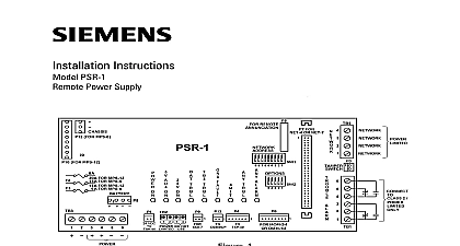
Fire Safety MME 3 in the upper right hand See Figure 1 MSE 2 in the upper right hand See Figure 1 RCC 1 1F in the lower right corner See Figure 2 In a special application which is on page 7 the PS 5N7 be used as a source of in a remote extender used to house extra Instructions PS 5N7 Interface 5V Power Supply Model PS 5N7 from Siemens Building Inc permits remote mounting the MXL annunciator modules MKB 1 and RCC 1 1F In addition when the is used with a PIM 1 it provides an for a remote printer that can be or unsupervised Each PS 5N7 one network node PS 5N7 can be used in an MME 3 MSE 2 an RCC 1 1F enclosure Mount the PS 5N7 the following enclosures as described below the Note at the top of page 2 if using a Wiring Diagram in MME 3 or MSE 2 Without a PIM 1 1 Building Technologies Inc Fernwood Road Park New Jersey 07932 315 092729 13 Building Technologies Ltd Kenview Boulevard Ontario L6T 5E4 CN Wiring Diagram in the RCC 1 1F Enclosure Without a PIM 1 2 male female standoffs are provided in backbox in the correct location for the PS 5N7 Place the PS 5N7 the existing female standoffs Fasten it the threaded portion of the standoffs screws Use the cable provided See 1 and 2 to connect P1 on the to P1 on the ANN 1 a PIM 1 is used in the config refer to the instructions the PS 5N7 with a PIM 1 support a remote printer use a PIM 1 the PS 5N7 The PIM 1 and PS 5N7 have the mounting holes using a PIM 1 with the PS 5N7 in MME 3 or MSE 2 backbox See Figure 3 Mount the PIM 1 first as shown Use the four male female standoffs with the PS 5N7 as screws Attach the PIM 1 to the female Connect the cable from P1 of the board to P1 on the PIM 1 Next mount the PS 5N7 on the same using the four screws from PIM 1 kit Attach the cable supplied with the to P2 on the PIM 1 Plug the cable from P2 of the PIM 1 P1 of the PS 5N7 see Figure 3 Wiring Diagram in MME 3 or MSE 2 With a PIM 1 3 Cabling Diagram in the RCC 1 1F Enclosure With a PIM 1 4 using a PIM 1 Module with the in an RCC 1 1F Enclosure See 4 and 5 Mount the PS 5N7 to the right of the in the bottom of the enclosure Refer to the RCC 1 1F Installation P N 315 095364 for on the cabling connections additional information refer to PIM 1 Instructions P N 315 091462 Connection PS 5N7 requires a DC input of 14 31 VDC input is available from the MMB or the Refer to Figure 5 for the correct instructions the PS 5N7 with Style 4 Network Connections screw terminals 1 and 2 for Network A NOT USE wire terminals 3 and 4 in this See Figure 5 for additional information Refer to the PSR 1 Instal Instructions P N 315 090911 for more on Style 4 networks PS 5N7 with Style 7 Wire Network Connections not place the PS 5N7 module in the last on a Style 7 Network Use a NET 7 each end of the network to provide proper screw terminals 1 and 2 for Network A 3 and 4 for Network B Refer to 5 for wiring instructions Restrictions MXL supports a maximum of 64 network Each module in the list below repre one node Do not plan a system with than 64 of these modules one allowed per system total wire resistance in both wires of the pair cannot be more than 80 ohms If the system has more than 32 nodes an module must be used CONNECTIONS VDC input VDC 300mA max VDC output VDC 500mA max P P max 150mA max to the following Installation as needed 315 095097 315 048860 315 090911 315 085062 315 093495 315 099082 Manual P N 315 092036 with PS 35 BN4 002 UL 9 12 3 6 1 2 18 19 Use a minimum wire gauge of 18 AWG Use a maximum of 80 ohms per pair of for the network connections Use twisted pair or shielded twisted pair for connections Terminate the shield ONLY at the MMB Eliminate all Network B wiring for Style 4 DO NOT place the PS 5N7 at the end of network Style 7 only This configuration is power limited to NFPA according to NEC 760 Refer to Wiring Specification for MXL MXL and MXLV Systems P N 315 092772 6 or higher for additional wiring Power Supply and Network Wiring Diagram 5 Rmax result obtained with this equation the total of all wire resistance in ohms in 24 VDC supply lines following power supplies are compat with the PS 5N7 They are listed with maximum output current Imax amp amps amps amps amps maximum module current is shown in 1 below 1 Module Current 20mA the wire resistance is calculated use 2 below to determine the maximum cable length See Figure 5 2 Resistance RATINGS VDC Power may connect multiple PS 5N7s to the 24V power supply as long as the total loss is within specified limits Follow the given below to calculate the line losses to follow these guidelines result in excessive voltage that cause improper or no of the system determine the total line loss and there the maximum cable length permitted the following values and limits maximum allowable voltage due to wire resistance Vmax must be more than 4V See Table 2 total alarm current drawn by PS 5N7 modules connected to the 24 supply If a PIM 1 is used in the include its current See the Imax for the approved power supplies the bottom of this column See Table also value of wire resistance results in a 4 volt drop due to Imax calculate the total line loss use the fol equation Vmax Imax Where Vmax 4V in all cases the PS 5N7 to Drive an OMM 1 order to add Voice hardware to a remote use a PS 5N7 module to drive an if the following conditions apply The remote enclosure is not to the MMB and There are multiple MXLs that are not a PS 5N7 and an OMM 1 under conditions provides power as well as with the MXLV Refer to 6 for the correct wiring information this configuration all equipment for this in the same 555 190967 Restrictions max current 500mA No to Wiring Specification MXL MXL IQ and MXLV P N 315 092772 6 or higher for wiring information to the following Installation for further information PSR 1 P N 315 090911 OMM 1 P N 315 090267 6 Connection to an OMM 1 Use the PS 5N7 Module in a Remote Extender Enclosure to Wiring Specification for MXL MXL IQ MXLV Systems P N 315 092772 revision 6 higher for additional wiring information additional information on this configuration to the following Installation Instructions 315 092083 315 093782 315 092064 the PS 5N7 in a Remote Extender Enclosure 7 Building Technologies Inc Fernwood Road Park New Jersey 07932 315 092729 13 Building Technologies Ltd Kenview Boulevard Ontario L6T 5E4 CN