Siemens PSC-17C 17 Amp Power Supply Extender, Installation Instructions

File Preview
Click below to download for free
Click below to download for free
File Data
| Name | siemens-psc-17c-17-amp-power-supply-extender-installation-instructions-8512409637.pdf |
|---|---|
| Type | |
| Size | 1.06 MB |
| Downloads |
Text Preview
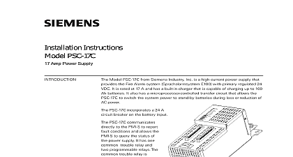
Installation Instructions PSC 17C Amp Power Supply S54505 B11 B1 S54505 B11 C1 Model PSC 17C from Siemens Industry Inc is a high current power supply that the Fire Alarm system Sprachalarmsystem E100 with primary regulated 24 It is rated at 17 A and has a built in charger that is capable of charging up to 100 batteries It also has a microprocessor controlled transfer circuit that allows the to switch the system power to stand by batteries during loss or reduction of power PSC 17C incorporates a 24 A breaker on the battery input PSC 17C communicates to the PMI S to report conditions and allows the to query the status of power supply It has one trouble relay and programmable relays The trouble relay is to activate when between DAC PMI or DAC and power is lost PSC 17C mounts at the of the enclosure of the system and occupies of the E100 Mounting MP M 1 17 Amp Power Supply PSC 17C features are as follows AC power input 120 VAC 240 VAC 50 Hz 60 Hz Switch Mode Power Converter Factor Correction Battery Charger Output power of 17 A 24 VDC separate power output terminals one power limited terminal with 4 A 24 VDC capacity and one non power limited terminal with 17 A 24 capacity total not to exceed 17 A Edition 5 315 050284 3 PSC 17C occupies one network address in the CAN network and has four functional the Controller the Charger the Power Supply and the Interface Board Input Supervision with Battery Back up In the event of reduction or cut of AC power the microprocessor controller transfer circuit will switch the power to stand by batteries output terminals have current measurement capability resettable current protection circuits for overload and short circuit to CC 5 CC 2 System bus 6.2 VDC 2 A max power limited to the system bus 24 VDC 2 A max power limited to the system bus subject to a A total current limit via CAN protocol common trouble relay and two programmable relays with 2 A ratings Controller determines the activation of the Charger and monitors the status of Power Supply ground fault conditions loss of network communication 24 VDC overload and the status of the battery This information is relayed to the Interface when applicable and communicated to the PMI S for system report The Controller also allows the PMI S to query the state of the power supply and current load and can send a diagnostics command to the PSC 17C It also pro the control of the relays Power Supply has an Off line switch mode power converter and power factor circuit to improve conductive RF emission at low frequency It is designed take voltage inputs of 120 VAC 240 VAC at 50 Hz 60 Hz and has one resettable breaker that can also be used as a battery power switch Charger monitors and maintains the battery This circuitry utilizes several charging depending upon the state of the batteries The Charger monitors the batter and determines which of the charging modes to activate It also has the capability check the state of the battery through diagnostic testing PSC 17C has one reset switch seven LEDs three rotary switches located below the LEDs to set the CAN network address one circuit breaker four blocks four terminal connections two 60 pin flat ribbon connections and a selection jumper as shown in Figure 2 The ribbon cable connections are used connect the PSC 17C with the PSX 17C or a Card Cage CC 2 CC 5 reset switch is located on the top of the front panel Pushing the reset switch re the PSC 17C operation LEDs located at the top left of the module and are defined as follows ON illuminated indicates that the PSC is powered from the AC mains When indicates that the PSC 17C is from the battery OFF illuminated indicates that the microprocessor has failed FAIL B755 Edition 5 315 050284 3 Blocks and Indicators USED LIMITED 4A FAIL OFF illuminated indicates that CAN with the PSC 17C has FAIL used for E100 applications OFF PSX 17 C CC 5 CC 2 PSX 17 C CC 5 CC 2 V 4 A FAIL FAIL FAIL FAIL FAULT 17A FAIL 4A FAIL O POWER OUTPUT 17A Max OUTPUTS A 30 VDC A 125 VAC A 250 VAC LOAD 2 Blocks Controls and Indicators S S SHIELD TIE POINT AT ONE ONLY 3 Wiring Diagram FAULT V 17 A FAIL OFF illuminated indicates that the has detected either a negative positive ground fault on its outputs OFF illuminated indicates that the 24 non power limited output TB4 has trouble condition or the PSC 17C has the 24 VDC output due to overload or short circuit OFF illuminated indicates that the 24 power limited output TB3 has a condition or the PSC 17C has the 24 VDC power output to current overload or short circuit rotary dial switches located directly below the LEDs are to set the CAN network address of the PSC 17C terminal blocks of the PSC 17C are defined as follows See 2 3 and 4 1 2 and 3 provide connection to the FMT S riser 4 5 and 6 provide an output to the monitor speaker in a mounted LVM SS HS 7 8 and 9 provide an input from the microphone of a mounted LVM SS HS or LVM D 10 11 and 12 provide an external CAN network connection outputs 1 for Trouble and 2 User programmable relays that are to NOT USED by default These outputs are rated 2 A 30 VDC 0.5 120 VAC 0.25 A 250 VAC Resistive Load Only normal system operation the trouble relay is controlled by the However if the CAN fails and the initiating card cannot with the PMI S the PSC 17C will control the TROUBLE The User programmable relays are activated by the PMI S logic as programmed by the Zeus tool When the system is normally these relays are controlled by the output logic See Figure 4 Edition 5 315 050284 3 2 1 IN 4 Wiring Diagram VDC Power Limited Output Terminal terminal output is limited to 4 A When it is exceeded it will shut light its associated diagnostics LED and send a fault condition to PMI S output is normally connected to the modules and cards located on door of the enclosure or to remote CAN network modules This is power limited All wiring must be in accordance with local codes See Figure 2 Voltage 24 VDC Current 4 A max terminal terminal VDC Non Power Limited Output Terminal terminal is non power limited and can supply up to 17 A When the draw is exceeded it shuts down lights its associated LED and a fault condition to the PMI S output is normally connected to the inputs of the CC 5 or Zone Modules This output must remain within the enclosure All must be in accordance with local building codes See Figure 2 Voltage 24 VDC Current 17 A max terminal terminal to sense the battery temperature used the back up battery to the PSC 17C Battery size has to be to ensure that the battery size can support the system load battery bac