Siemens PSC-ISO-CBL PSC-12 Isolating Cable, Installation Instructions

File Preview
Click below to download for free
Click below to download for free
File Data
| Name | siemens-psc-iso-cbl-psc-12-isolating-cable-installation-instructions-6207591834.pdf |
|---|---|
| Type | |
| Size | 680.05 KB |
| Downloads |
Text Preview
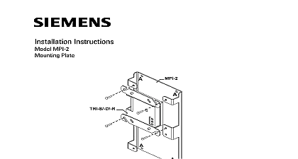
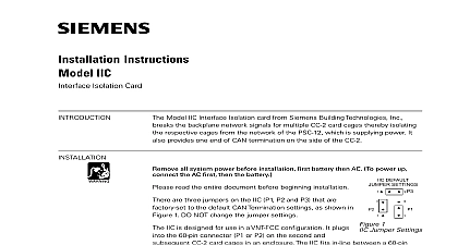
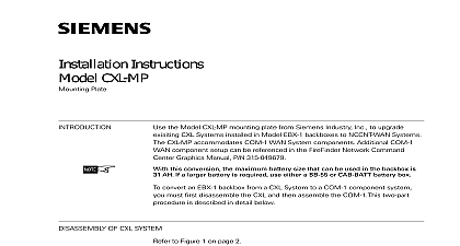
SIEMENS Instructions PSC ISO CBL Isolating Cable on the system configuration the 100AH battery size for a single PSC 12 may be to support the desired equipment in a given Using the model PSC ISO CBL a second can be installed eliminating the need to add a CAB 1 2 3 enclosure and the NIC Cs needed to them The PSC ISO CBL cable isolates the and 24V power supplies between the PSC 12s are sharing the same backplane Depending on the of the batteries for each PSC 12 either one or two enclosures will be required 10 introduces the concept of a Primary PSC 12 and a Non Primary PSC 12 PSC 12s must be interconnected via the NIC C Non Primary PSC 12s must be to a Primary PSC 12 via the PSC ISO CBL cable A single enclosure with a Primary PSC 12 and a Non Primary PSC 12 does require a NIC C Zeus each PSC 12 either Primary or Non Primary must be installed in its own This is necessary for the proper calculation of power supply loading and size In the actual installation the Primary and Non Primary PSC 12s will be in the same enclosure Careful attention must be paid to the amount of equipment in the two Zeus will not be able to detect that the equipment may not fit into the single enclosure Industry Inc Technologies Division is no restriction as to which modules can be connected to either a Primary of Non PSC 12 however in Zeus each primary PSC 12 in a multi enclosure system Figure 5 must have a NIC C in its enclosure the Primary and Non Primary PSC 12s adjacent to one another in the center of the or in the lower right hand corner of the CAB 2 3 Install the PSC ISO CBL theses two power supplies It is not possible to split the power within a CC 5 of CC 2 All of the within a single card cage must be powered from the same PSC 12 the equipment in a manner that makes it easy to identify which PSC 12 is power to which modules A vertical split is recommended in the CAB 2 a split by row is best in a CAB 3 to Figures 2 5 for typical cable routing Fault detection must be provided by only one PSC 12 in an enclosure Disable fault detection on all Non Primary PSC 12s by moving the jumper on P10 from Enable position 1 2 to the Disable position 2 3 See Figure 1 for the location of on the PSC 12 1 PSC 12 Ground Fault Enable Disable Jumper P10 Location Industry Inc Technologies Division Pin Each PSC 12 requires its own battery set Depending on the battery size one or two battery boxes are needed 2 Single CAB 1 enclosure Industry Inc Technologies Division ribbon cable these CC 5s Pin Each PSC 12 requires its own battery set Depending on the battery size one or two battery boxes are needed 3 Single CAB 2 enclosure Industry Inc Technologies Division ribbon cable these CC 5s Pin Each PSC 12 requires its own battery set Depending on the battery size one or two battery boxes are needed 4 Single CAB 3 enclosure Industry Inc Technologies Division ribbon cable these Pin next ribbon between CC 5 s Pin ISO CBL Each PSC 12 requires its own battery set Depending on the battery size one or two battery boxes are needed per CAB enclosure 5 Multiple enclosures Industry Inc Technologies Division of Power Limited and Non Power Limited Wiring in accordance with local codes and Article 760 of the NEC NFPA 70 latest In compliance with NEC Article 760 all power limited fire protective signaling must be separated by a minimum of inch from all of the following located the control panel Electric Light Circuits Power Circuits Class 1 or Non Power Limited fire protective signaling conductors Limited and Non Power Limited circuits leaving the enclosure must be in separate to Figures 6 8 for the proper routing of Power Limited Dashed Lines and Non Limited Solid Lines wiring within the CAB 1 2 3 enclosures I O 4A I O Limited Power Circuit 1 2 Industry Inc Technologies Division 6 CAB 1 Card I O Card I O 4A 4A Limited Power Circuit 1 2 7 CAB 2 Industry Inc Technologies Division 8 CAB 3 Industry Inc Technologies Division Ratings The total Standby current for the Primary and Non Primary PSC in a single enclosure must not exceed 5A and the total Alarm current must not 12A PSC 12 either Primary or Non Primary will be located in a unique enclosure in Zeus will perform battery size and power supply loading calculations Perform the following steps to determine the proper battery size and loading for the combination of the Primary and Non Primary PSC 12s that be installed in a single enclosure Zeus generate a Power Battery Calculation Report This report is under Tools Report Generation System Power Battery See the example below Enclosure 1 contains a Primary PSC 12 and 2 contains a Non Primary PSC 12 Observe the calculated battery size for each enclosure This is the required battery for either the Primary PSC 12 13.841AH in the example or the Non PSC 12 11.292AH in the example Depending on the battery size either or two battery boxes may be required For each pair of Primary and Non Primary PSC 12s that will be in the same in the final system add the calculated Standby currents together In the the total is 0.296AMP 0.101AMP 0.397AMP The sum must not 5A For each pair of Primary and Non Primary PSC 12s that will be in the same in the final system add the calculated Alarm currents together In the the total is 4.453AMP 6.258AMP 10.711AMP The sum must not 12A Industry Inc Technologies Division page has been left intentionally blank Industry Inc Technologies Division page has been left intentionally blank Industry Inc Technologies Division Park NJ Ontario L6T 5E4 Canada Canada Limited Technologies Division Kenview Boulevard ID A6V10423333 en a A5Q00060425