Siemens PSR-1 Remote Power Supply, Installation Instructions

File Preview
Click below to download for free
Click below to download for free
File Data
| Name | siemens-psr-1-remote-power-supply-installation-instructions-6340921785.pdf |
|---|---|
| Type | |
| Size | 1.08 MB |
| Downloads |
Text Preview
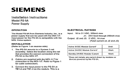
Installation Instructions PSR 1 Power Supply 1 Remote Power Supply Model PSR 1 from Siemens Industry Inc Figure 1 is a microprocessor controlled power supply and battery charger used the MXL System It operates with an or MPS 12 to provide 6 or 12 amps of power for various MXL mod addition the PSR 1 acts as an interface remote option modules and the MXL used with a NET 4 plug in communica module See Instructions P N 315 090909 NET 7 plug in communication module See P N 315 091914 PSR 1 can also be used to power an annunciator driver set In addition the can be used as an auxiliary power supply a standalone mode without an MXL PSR 1 has LED status indicators for ON 5V AUX ON 24V ON BAT TRBL TRBL Class A power limited output for the and PS 5 GND FAULT XMIT ANY and ANY ALARM The PSR 1 has two used for common alarm and common These relays also can be programmed local alarm and local trouble using CSG M additional information on the MXL MLV refer to the MXl MXLV Manual 315 092036 Industry Inc Technologies Division Park NJ 315 090911 23 Building Technologies Ltd Safety Security Products Kenview Boulevard Ontario 5E4 Canada CONNECTIONS all system power before installation battery and then AC To power up first the AC and then the battery Power power for the PSR 1 is provided by the or MPS 12 Both of these mount in the right hand corner of the MXL enclosure the instructions below for the appropriate supply Install the MPS 6 See MPS 6 Instruc P N 315 090334 With the AC mains connect the MPS 6 power cable to of the PSR 1 Be sure that the jumper is installed in P10 of the PSR 1 If jumper is not installed the PSR 1 will a permanent AC fail or indicate auxilia power voltage is low F2 to a 15A fuse P N 105 224090 F3 to a 6A fuse P N 105 268095 Install the MPS 12 See MPS 12 P N 315 092030 Remove and the jumper assembly installed in P10 of PSR 1 Disconnect the AC mains Connect MPS 12 power cable to P10 of PSR 1 Calculations backup is a requirement for the MXL To the size battery you must use follow procedures listed below The MXL can a battery of up to 55 amp hours A bat size calculation form is provided on page 3 NFPA 72 Municipal Tie and 72 Remote systems multiply the total system by 60 and record it at that Total AH FM Appoved Deluge PreAction multiply the total system current by and record it at that Total AH location Multiply the AH Total by 1.3 to obtain the final amp hour capacity and record it Battery Size battery models are UL listed for use with MXL 15 AH set of 12V 31 AH set of 12V 55 AH 65 AH or 75 AH Although larger batteries may be used as the 55 AH capacity must be used for battery requirements the battery that meets or exceeds the final battery amp hour rating Use an battery box with the BTX 2 model not connect the batteries at this time Supply Load Calculations ensure that the power supply is not over complete the worksheet on page 4 Enter the quantity of each module in the Record all the modules required in the form Caclulate both the 24V and 5V loads for each the following page Calculate each row across and place the total Total the Active 24V and Active 5V columns the right column Total Standby 24 VDC Current Total the right hand column and record it at bottom of the form opposite Total Current For NFPA 72 Local and 72 Proprietary multiply the total system current by and record it at that Total AH location Ensure that both totals are within the power output ratings in the table below SUPPLY OUTPUT RATINGS 24 VDC 5 VDC Current Current amps amps mA mA Use this column for size Power is supplied by separate UPS EOL currents The following draw no 24 current and do need to be in the calculations The following modules Use this column to total current 24 VDC supply to sure it is not Use this column to total current 5 VDC supply to sure it is not PSR 1 supplies 5V at 24V at 6A 24V at 12A no current from the 5 VDC or 24 power supplies do not need to be in these THE OPTION ON SWITCH S2 Figure 2 Disable the Network S2 1 Disable Network Switch located at S2 1 or disables the network connection NETWORK SWITCH SETTINGS or OFF or ON not connected to the MXL network