Siemens PSX-12 12 Amp Power Supply Extender, Installation Instructions

File Preview
Click below to download for free
Click below to download for free
File Data
| Name | siemens-psx-12-12-amp-power-supply-extender-installation-instructions-0627543198.pdf |
|---|---|
| Type | |
| Size | 821.25 KB |
| Downloads |
Text Preview
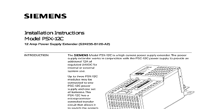
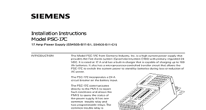
Installation Instructions PSX 12 Amp Power Supply Extender Model PSX 12 from Siemens Industry Inc is a high current power supply The power supply extender works in conjunction with the PSC 12 power to provide an additional 12A of regulated 24VDC for internal or external use to three PSX 12 modules be connected to one power supply and set of batteries The has a microprocessor transfer circuit that it to switch the power to stand batteries during loss reduction of the AC PSX 12 incorporates 18A circuit breaker on battery input PSX 12 communi directly to the PMI XLS Desigo Safety Modular Cerberus Modular to report conditions and allows the PMI PMI 2 PMI 3 XLS FCM2041 U2 Desigo Fire Modular FCM2041 U3 Cerberus PRO Modular to query the status of the supply extender 1 12 Amp Power Supply Extender PSX 12 mounts at the back of the enclosure of the FireFinder XLS Desigo Fire Modular Cerberus PRO Modular system and occupies one location on the in the backbox or on the optional FireFinder XLS Desigo Fire Safety Modular PRO Modular Mounting Plate CAB MP power input 120VAC 240VAC 10 60Hz 50Hz Switch Mode Power Converter Factor Correction Output power of 12A 24VDC separate power output terminals one power limited terminal with 4A 24VDC capacity and one non power limited terminal with 12A max 24VDC capacity total not to exceed 12A Inc Inc Inc Industry Inc Inc TTTTTececececechnologies Di Di Di Division Di PSX 12 features are as follows 315 034120 20 output terminals have current measurement capability resettable current protection circuits for overload and short circuit to CC 5 CC 2 System bus via HNET protocol PSX 12 occupies one network address in the HNET network and has three func components the Controller the Power Supply Extender and the Interface Board Controller monitors the status of the Power Supply Extender loss of network 24VDC terminal overload and the status of the battery This informa is relayed to the User Interface where applicable and is communicated to the for system reporting The Controller also allows the PMI PMI 2 PMI XLS FCM2041 U2 Desigo Fire Safety Modular FCM2041 U3 Cerberus PRO to query the state of the power supply extender and its current load and send a diagnostics command to the PSX 12 Power Supply Extender has an Off line switch mode power converter and power correction circuit to improve conductive RF emission at low frequency It is to take voltage inputs of 120VAC 240VAC at 60Hz 50Hz and has one circuit breaker that can also be used as a battery power switch Interface Board provides diagnostics LEDs system connections and the terminal on the PSX 12 Blocks and Indicators PSX 12 has one reset switch six LEDs three HNET CAN address switches one breaker two terminal blocks two terminal connections and two 60 pin flat connections as shown in Figure 2 reset switch is located on the top of the front panel Pushing the reset switch re the PSX 12 operation LEDs located at the top left of the module and are defined as follows FAIL FAIL FAIL 12A FAIL ON When illuminated indicates the PSX 12 is powered from the AC When flashing indicates that the is powered from the battery OFF When illuminated indicates the module microprocessor has failed OFF When illuminated indi that CAN communication with the has terminated applicable only PSX 12 resides in a CAN network OFF When illuminated indicates the HNET communication with the has terminated and the card goes degrade mode applicable only when PSX 12 resides in the HNET network OFF When illuminated indicates the 24VDC non power limited output Industry Inc Technologies Division 315 034120 20 LIMITED OUTPUT 4A 4A FAIL Yellow a trouble condition or the PSX 12 has the 24VDC output due to overload or short circuit OFF When illuminated indi that the 24VDC power limited has a trouble condition or the has disconnected the 24VDC output due to current overload or circuit Three rotary dial switches located directly below the LEDs are used set the HNET CAN network address of the PSX 12 terminal blocks of the PSX 12 are defined as follows refer to 2 FAIL FAIL FAIL 12A FAIL 4A FAIL PSC 12 CC 5 CC 2 PSC 12 CC 5 CC 2 NON POWER OUTPUT 12A Max and negative ground fault detected at ohms for TB3 terminals 1,2 ohms for TB4 terminals 1,2 2 Blocks Controls and Indicators Power Limited Output Terminal This terminal is limited to 4A When it is exceeded it will shut light its associated diagnostics LED and send a condition to the PMI PMI 2 PMI 3 XLS Desigo Fire Safety Modular FCM2041 Cerberus PRO Modular output is normally connected to the modules and located on the door of the enclosure or to the CAN network modules This output is power to NFPA 70 per 760 All wiring must be in with Article 760 of NEC or local building See Figure 2 Voltage 24VDC 10 15 Current 4A max terminal terminal Non Power Limited Output Terminal This is non power limited and can supply up to When the current draw is exceeded it shuts lights its associated LED and sends a fault to the PMI PMI 2 PMI 3 XLS FCM2041 U2 Fire Safety Modular FCM2041 U3 Cerberus Modular output is normally connected to the input terminals the CC 5 All wiring must be in accordance with 760 of NEC or local building codes See Figure 2 Voltage 24VDC 10 15 Current 12A max terminal terminal total cumulative sum of the 24VDC output power limited non power limited not exceed 12A Over current draw will initiate a PSX 12 shut down Industry Inc Technologies Division 315 034120 20 PSX 12 installation kit has the following components The main AC power line must be turned OFF prior to installation the back up battery to the PSX 12 apply AC power first followed by the battery input connector from the PTB P4 P5 the PSX 12 to the system It is a straight through connection the two connectors It contains the communication signals and signal bus that is necessary for the proper operation of the connectors are power limited If the PSX 12 is located in a row in the enclosure an optional extended ribbon cable BCL P N 599 633997 must be used following part is optional the PSX 12 is not located in the same row in the backbox or on the same as the CC 5 an extended 60 pin flat ribbon cable Model BCL 599 633997 is required following components must be set prior installing the module in the enclosure that the dedicated circuit breaker for the PSX 12 is turned OFF at the mains Circuit Breaker Set this circuit breaker to the OFF position Address Switch Set the three digit HNET CAN network address the PSX 12 using the three rotary dial address switches located near the of the front panel Refer to Figure 2 for the location of the The address for the PSX 12 must be the same as the address for it in the Zeus Programming Tool To set the address turn the