Siemens PTB Power Termination Board, Installation Instructions

File Preview
Click below to download for free
Click below to download for free
File Data
| Name | siemens-ptb-power-termination-board-installation-instructions-6459782031.pdf |
|---|---|
| Type | |
| Size | 656.36 KB |
| Downloads |
Text Preview
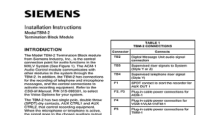
Installation Instructions PTB Termination Board Model PTB Power Termination Board from Siemens Industry Inc shown in 1 filters the power from the incoming AC mains and distributes it to the PSC power supply and the optional PSX 12 power supply extender 1 Power Termination Board Main Input Output To Next PTB Blocks terminal blocks of the PTB are defined as follows The main AC power line must be turned OFF prior to installation connectors of the PTB are defined as follows power connection AC adapter P N 500 633992 required connection connection PSC 12 or PSX 12 PSC 12 or PSX 12 apply AC power first followed by the battery 315 034877 4 Industry Inc Technologies Division installation kit has the following components to Figure 2 one PTB can be mounted in a CAB 1 one or two PTBs can be mounted in a or CAB 3BB RB the four holes on the PTB Power Termination Board over the studs in the desired location in the bottom portion of the CAB the PTB in place with the four 10 hex nuts supplied PTB ON THREADED STUDS VOLTAGE VOLTAGE PTB ON THREADED STUDS 2 The PTB In CAB 2BB RB Or CAB 3BB RB Industry Inc Technologies Division 315 034877 4 WIRING BATTERY and AC prior to working on equipment to Figure 3 in accordance with local codes and Article 760 of the NEC NFPA latest edition compliance with NEC all power limited fire protective signaling conductors must separated a minimum of a 1 4 from all of the following wiring located within a panel light 1 or non power limited fire protective signaling conductor to the CAB1 Installation Instructions P N 315 033007 or the CAB2 BB RB and Installation Instructions P N 315 033009 as applicable for wiring to comply with NEC codes the AC mains to the PTB TB1 as follows the Green earth ground wire from the AC mains to the earth lug on the enclosure chassis must install the PSC 12 PSX 12 in the row and position directly above the PTB connects to it 12 inch cable connects the PTB to the PSC 12 PSX 12 Plug one end of AC assembly cable into P12 on the PSC 12 PSX 12 Plug the other end the cable into P4 or P5 on the PTB When two PTBs are used in the same enclosure CAB2 BB RB or only wire as shown in Figure 3 using 14 AWG minimum 10 maximum gauge wire the screw terminals of TB1 and gently pull AC connection to verify the AC line is properly connected to the PTB Industry Inc Technologies Division 315 034877 4 L A C K H I T E R E E N WIRE ASSEMBLY 600 134264 CABLE THIRD SECOND PSC 12 OR PSX 12 N GND N GND OUTPUT NEXT PTB MAIN 3 Wiring FOR SECOND PTB OR CAB3 BB RB ONLY SUPPLIED GAUGE WIRE OUTPUT NEXT PTB MAIN LUG IN THE 120 VAC 120 VAC GROUND GREEN green earth ground wire from the AC Mains MUST be connected to the gound lug located in the enclosure directly below where the PTB is provides the same AC voltage as the input mains on TB1 Care must be taken using this output because a short circuit at this terminal can shut down the line connection of the fire alarm panel RATINGS CE applications in Cerberus E100 systems refer to Instruction A24205 A334 B844 English or A24205 A334 A844 German Industry Inc Technologies Division Park NJ Canada Limited Technologies Division Kenview Boulevard Ontario L6T 5E4 Canada Geb Co oHG M 315 034877 4