Siemens RCC-3 RCC-3R RCC-3C RCC-3F RCC-3FC RCC-3FR Remote Command Center, Installation Instructions

File Preview
Click below to download for free
Click below to download for free
File Data
| Name | siemens-rcc-3-rcc-3r-rcc-3c-rcc-3f-rcc-3fc-rcc-3fr-remote-command-center-installation-instructions-7014538629.pdf |
|---|---|
| Type | |
| Size | 761.80 KB |
| Downloads |
Text Preview
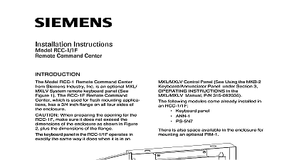
Installation Instructions RCC 3 3R 3C 3F 3FC 3FR Command Center Model RCC 3 3R 3C Remote Command from Siemens Industry Inc is an optional System remote keyboard panel See 1 The RCC 3R is red and will be re to in the remainder of this document as RCC 3 The RCC 3F 3FC 3FR Remote Center which is used for flush applications has a 3 4 inch flange on four sides of the enclosure The RCC 3FR is and will be referred to in the remainder of document as the RCC 3F When preparing the opening for the make sure it does not exceed the of the enclosure as shown in Figure 2 the dimensions of the flange panel in the RCC 3 3C 3F 3FC has a multi display that continuously updates information the system event status If there are events alarms security conditions and or troubles the highest event that occurred displays on the The user can view up to 8 events at a and can scroll through the complete list the Up to the More Info key For further information keys located and Down E L P I DE R I N T MP PA CE S P A CE N T E R N T R E R E A R F FA CE R panel lens 1 Remote Command Center Industry Inc Technologies Division Park NJ 315 048665 7 Building Technologies Ltd Safety Security Products Kenview Boulevard Ontario 5E4 Canada holes places for panel 2 the RCC 3 3F the operation of the MXL Multi Line Keyboard Panel refer to the MXL Keyboard Panel Operating Instructions P N 315 and Section 3 OPERATION in the Manual P N 315 092036 keyboard display panel has keys for the functions Acknowledging fire alarms ALARM ACK cid 127 Silencing audibles AUD SIL cid 127 Acknowledging supervisories SUPV ACK cid 127 Acknowledging troubles TRBL ACK cid 127 Acknowledging security conditions SEC ACK is also a separate key for resetting the Panel RESET 10 digit phone style keypad allows entry of three levels of user passwords It is also to perform specific menu driven operations well as programming and maintenance UP and DOWN keys located next to the INFO key allow the user to scroll forward backwards through the entire list of events SPACE key allows the user to input ad faster by enabling them to reduce key presses of the key MORE INFO key allows the user to instantly all relevant information about the highlighted which is displayed in the last three lines of screen user can access the MXL Control menu by the ENTER key panel has System status indicator LEDs ALARM and TROUBLE LEDs function even the main processor fails See Figure 1 remove all power before installation the battery and then the AC RCC 3 3C 3F 3FC comes with the key panel installed in the enclosure and clear lens installed in the door as shown in 1 KEYBOARD 3 3 3 OPTION OPTION 2 3 4 5 2 3 4 5 3 3 3 View of Keyboard Display Panel in RCC 3 3F 3 mounting the RCC 3 3C 3F 3FC the four nuts from the keyboard panel place them to one side Carefully lift the up and off the standoffs Set the panel to side the following when mounting the cid 127 Mounting height for visual and manual to the keyboard display panel cid 127 Weight and size of the enclosure cid 127 mounting codes Fasten the backbox securely to a clean dry and vibration free surface using four mounting holes provided Position backbox clear of obstructions so that the opens freely and the indicators and are easily accessible Set the Network Address for the RCC 3 the three ten position rotary switches S2 and S3 located on the back of the panel as shown in Figure 3 example to set the switches to address set S1 to 2 set S2 to 4 and set S3 to 8 possible addresses for this module are 259 250 and 251 is no need to set supervision on the because it is by default supervised No unsupervised MKB 1 2 3 4 are allowed the same address as an RCC 3 3C 3F Unsupervised applications require the of the MKB 1 2 3 4 and they must all set to the same address Pull all field wiring into the backbox and the wiring to the approximate location which it will go Remove the connector plugs from J8 Attach wiring to the connector plugs in positions and 2 for Style 4 refer to Figure 4 and 1 2 3 and 4 for Style 7 refer to 5 and 6 Always connect position 5 Chassis GND Earth GND Remove the connector plugs from J12 the field wiring to the connector plugs sure that position 1 on J12 is for and position 2 on J12 is for 24VDC To adjust the contrast and brightness of the use pots VR1 and VR2 respectively on the back of the keyboard display Refer to Figure 3 PRINTER EITHER A SERIAL OR PRINTER ONLY ONE CAN BE CONNECTED THE SYSTEM PRINTER BY DEFAULT OPTIONAL RCC 3 3 F Installation Only 140 820150 OHMS 1 4W 5 OHMS 1 4W 5 140 820150 EOL ASSEMBLY OHMS 1 4W 5 140 049099 24 VDC connections refer to the following terminations Used with PS 35 Model BN4 002 UL 9 12 3 6 1 2 18 19 Use a minimum wire gauge of 22 AWG Use a maximum of 80 ohms per pair of wires for network connections Use shielded twisted pair for network connections Terminate the shield ONLY at the MMB For MMB 1 2 Style 4 use a 120 Ohm 1 4W EOLR P N 140 820150 in positions 1 and on plug J8 MMB 3 Style 4 use Res EOL Assembly 120 1 4W 5 P N 140 049099 This configuration is power limited to NFPA according to NEC 760 The RCC 3 3C 3F 3FC MUST have an ground connected to the chassis Wire or conduit is not an acceptable ground any available unused unpainted stud on MMB for chassis grounding Refer to Wiring Specification for MXL MXL IQ MXLV Systems P N 315 092772 revision or higher for additional wiring information Maximum voltage 8V peak to peak current 150mA 4 Style 4 Wiring PRINTER EITHER A SERIAL OR PRINTER ONLY ONE CAN BE CONNECTED THE SYSTEM PRINTER BY DEFAULT OPTIONAL 140 820150 OHMS 1 4W 5 140 820150 OHMS 1 4W 5 140 820150 OHMS 1 4W 5 CHASSIS GND ON MMB 1 2 2 3 4 5 6 7 8 9 10 11 12 13 14 15 16 2 3 4 5 6 7 8 9 10 11 12 13 14 15 16 2 3 4 5 6 7 8 9 10 11 12 13 14 15 16 2 3 4 5 6 7 8 9 10 11 12 13 14 15 16 24 VDC connections refer to the following terminations Used with PS 35 Model BN4 002 UL 9 12 3 6 1 2 18 19 Use a minimum wire gauge of 22 AWG Use a maximum of 80 ohms per pair of for the network connections Use shielded twisted pair for network Terminate the shield ONLY at the MMB For Style 7 use a 120 Ohm 1 4W 5 P N 140 820150 in positions 1 and 2 positions 3 and 4 on plug J8 For Style 7 use a NET 7 card and refer to