Siemens REP-1 Network Repeater Module, Installation Instructions

File Preview
Click below to download for free
Click below to download for free
File Data
| Name | siemens-rep-1-network-repeater-module-installation-instructions-3407529618.pdf |
|---|---|
| Type | |
| Size | 811.04 KB |
| Downloads |
Text Preview
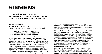
Installation Instructions REP 1 Repeater Module Model REP 1 from Siemens Industry is an MXL module that permits the to extend the distance of the MXL network as well as the distance of NIM 1R RS 485 network The REP 1 supports both Style 4 and Style 7 MXL network uses an RS 485 inter for its network wiring The RS 485 up to 32 nodes on each pair of See Note below A node is any location where network wires are con to the screw terminals an MXL System module REP 1 module reproduces the RS 485 on a new pair of wires The new makes it possible to add more nodes the system REP 1 Repeater module may be used to Add nodes to the end of a system by providing a repeated Add a Style 4 or Style 7 tap to a Add a Style 4 tap to a Style 7 or 1 Repeater PC Board Industry Inc Technologies Division Park NJ 315 092686 8 Building Technologies Ltd Safety Security Products Kenview Boulevard Ontario 5E4 Canada Repeater Operation to Figures 2A and 2B REP 1 has two independent 2 wire repeaters that permit the addition another 80 ohms of wire to a Style 4 by using the REP 1 at the end of the When an REP 1 Repeater is in there can be up to 64 nodes on that however two of the nodes are for the repeater module itself REP 1 module uses one node on each pair to which it is connected Al this decreases the 32 available on a network run the REP 1 module 31 new nodes on the repeated net REP 1 module occupies one node on original network and one node on the network in both Style 4 and Style wiring a T Tap to a System Figures 2C and 2D an REP 1 module is connected along a 4 or a Style 7 network the repeated can run in a new direction This of setup makes it possible to have a configuration on the network Style 7 to Style 4 in System Figure 2E Style 4 tap can be added to a Style 7 by using an REP 1 module This helpful when installing RCC 1s and in a Style 7 system if Style 7 is required for those modules an REP 1 is used to add Style 4 to a 7 network REP 1 connects to two thus adding 30 new nodes Control of System Size though the REP 1 supplies an node count in a system the total size is still controlled by the CSG M limit guarantees that the MXL System support the number of modules installed Figure 1 is one switch S1 and one jumper on the REP 1 that must be set before the REP 1 in the MOM 4 module the Switch on REP 1 S1 switch on the REP 1 has two available left side position 7 to 4 of the enables conversion from 7 to Style 4 Select the right side position of the switch if the REP 1 used as a repeater the Correct Position the JP1 Jumper REP 1 provides electrical isolation the local power supply and the lines The JP1 jumper on the has two positions relating to this and MMB Select the left side position PSR for jumper if the REP 1 is installed in enclosure with a PSR 1 This set protects ground fault isolation for system See CAUTION on the next Select the right side position MMB the jumper if the REP 1 is installed an enclosure with an MMB so as protect ground fault isolation circuits additional information on the MXL MXLV refer to the MXL MXLV Manual 315 092036 NIM 1R Network a REP 1 is used on a NIM 1R place the JP1 jumper in the position no matter in which type cabinet the REP 1 is installed RATINGS Repeater Style 4 Repeater Style 7 Running in One with Style 4 Running in Two with Style 4 Place a 120 ohm resistor 140 820150 where indicated 2 Basic Wiring Including of EOL resistors from Style 7 to Style 4 Figure 3 all system power before installa first battery and then AC To power first connect the AC and then the battery the REP 1 in the MXL card cage MOM 4 by inserting the REP 1 in the desired position MOM 4 is shipped with a card guide in for TB1 TB2 TB3 and TB4 on the board In addition an extra card is shipped with the REP 1 Place the card guide at the end of the terminal chosen for the REP 1 module To the card guide Loosen the appropriate screw in center of the MOM 4 Set the card guide in place mak sure the locating pin on the of the card guide is in the on the MOM 4 Tighten the screw on the MOM 4 secure the card guide the REP 1 by sliding it into card guides and firmly seat it in the card edge connector Limits not connect more than two REP 1s in for proper operation of the network be sure there are no more than two in series check that There are no more than two between any MXL and the MMB In an NIM 1R network there no more than two REP 1s any pair of NIM 1Rs the network Use 18 AWG minimum wire Limit maximum resistance per pair to 80 ohms Use shielded twisted pair Terminate the shield ONLY at the MMB enclosure The wiring is power limited according to NFPA 70 NEC 760 Maximum voltage is 8V P P Maximum current is 150mA Use the end of line resistor P N 140 820150 120 1 4W See Figure 2A for further information Refer to Wiring Specification for MXL MXL IQ MXLV Systems P N 315 092772 revision 6 higher for additional wiring information 2 3 Repeater 4 CONNECTIONS Repeater Figures 3 and 4 basic repeater connects to the network the end of the run A repeater can ex the distance of the network or can add nodes to the system If a basic is in place the original network at the REP 1 and is terminated with a resistor new repeated network begins at the and also has an end of line resis Figure 3 shows the connection for a 4 network The second half of the is not used in this configuration so has both sides terminated as shown Style 7 networks Figure 4 use both of the REP 1 Use 18 AWG minimum wire Limit maximum resistance per pair to 80 ohms Use shielded twisted pair Terminate the shield ONLY at the MMB enclosure The wiring is power limited according to NFPA 70 NEC 760 Maximum voltage is 8V P P Maximum current is 150mA Use the end of line resistor P N 140 820150 120 1 4W See Figure 2B for further information Refer to Wiring Specification for MXL MXL IQ MXLV Systems P N 315 092772 revision 6 higher for additional wiring information 4 Repeater 7 Figure 5 REP 1 can be connected anywhere a network run to provide a T tap the REP 1 between the two ends of primary network and do not use an device where the primary network to the REP 1 however the tapped side runs in two from the REP 1 do not use an of line resistor Instead place the of line resistors at the two ends of the network For Style 7 networks use second half of the REP 1 for the B side the network Repeat this method connecting the end of line resistors the B side of a Style 7 network from Style 7 to Style 4 Figure 6 REP 1 can be used to provide a Style tap on a Style 7 network Figure 6 shows Style 4 tap that begins at the REP 1 This can also be run in two directions if the of line resistors are connected to the of the Style 4 tap A typical use of this to either an RCC 1 1F or MOI 7 be for a group of annunciators where 7 wiring is not required for the annun but the rest of the system must be 7 Do not connect the Style 4 tap to Use 18 AWG minimum wire Limit maximum resistance per pair to 80 ohms Use shielded twisted pair Terminate the shield ONLY at the MMB enclosure The wiring is power limited according to NFPA 70 NEC 760 Maximum voltage is 8V P P Maximum current is 150mA Use the end of line resistor P N 140 820150 120 1 4W See Figure 2D for further information Refer to Wiring Specification for MXL MXL IQ MXLV Systems P N 315 092772 revision 6 higher for additional wiring information 5 in One Direction Style 4