Siemens SIM-16RC Supervised Input Module Ribbon Cable, Installation Instructions

File Preview
Click below to download for free
Click below to download for free
File Data
| Name | siemens-sim-16rc-supervised-input-module-ribbon-cable-installation-instructions-2056493871.pdf |
|---|---|
| Type | |
| Size | 643.61 KB |
| Downloads |
Text Preview
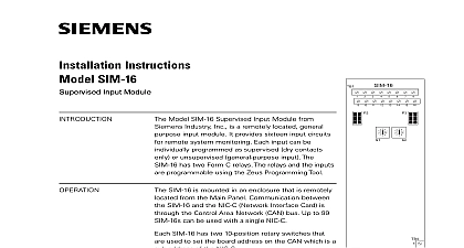
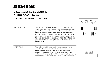
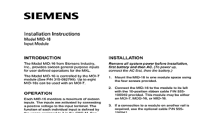
Installation Instructions SIM 16RC Input Module Ribbon Cable Model SIM 16RC Supervised Input Module Ribbon from Siemens Industry Inc is a remotely located purpose input module It provides sixteen input for remote system monitoring Each input can be unsupervised general purpose input The has two Form C relays The relays and the are programmed by inserting an SIM 16 in the Programming Tool must be programmed as unsupervised SIM 16RC is mounted in an enclosure that is located from the Main Panel Communication the SIM 16RC and the NIC C Network Interface or DAC NET is through the Control Area Network bus Up to 99 SIM 16RCs can be used with a NIC C or DAC NET SIM 16RC has two 10 position rotary switches that used to set the board address on the CAN which is a of the NIC C or DAC NET time a change of state of the input is detected a CAN message is sent to the NIC C or DAC NET A message from the NIC C or DAC NET directed to SIM 16RC controls the Form C relays Address Switches Set the board address for SIM 16RC using both of the ten position rotary located on the board See Figure 1 Each of addresses must be a sub address of the NIC C or and must be the same as the addresses in the Zeus Programming Tool 5 6 5 6 1 Supervised Module Ribbon SIM 16RC may be installed in a REMBOX When using REMBOX 2 or 4 mount the in one module space on a REMBOX2 MP P N 500 634211 or REMBOX4 P N 500 634212 using the four screws provided Refer to REMBOX2 MP Installation Instructions P N 315 034211 Up to 4 SIM 16RCs will fit a REMBOX2 up to 8 SIM 16RCs will fit in a REMBOX4 Inc Inc Inc Industry Inc Inc TTTTTececececechnologies Di Di Di Division Di 315 050715 1 to Figures 2 5 all system power before installation first battery then AC To power up the AC first then the battery SIM 16RC module is a node in the CAN bus SIM 16RC can be installed with or without an RNI Connect the CAN and 24V as shown in Figures 2 and 3 to 99 CAN modules in any combination can be connected to the CAN of each NIC C or DAC NET SIM 16RC module is shipped with one CCS cable connections for SIM 16RC modules are shown in the following table CAN bus requires a 120S termination at each end of the loop Refer to the NIC C Instructions P N 315 033240 for details about CAN termination ribbon cable for J1 and J2 is to be provided with the external unit CCS RNI P4 5 6 5 6 5 6 5 6 5 6 5 6 5 6 5 6 TERMINATOR 110 134215 WITH NIC C CCL 2 CAN Bus Connections With An RNI Industry Inc Technologies Division 315 050715 1 All wiring supervised All circuits are power limited article 760 of NEC The ribbon cables for J1 and must be within the same room within 20 ft in rigid conduit Wiring for TB3 and TB4 is min 16 AWG max CAN network max line 15S Refer to the NIC C Instructions P N for CAN termination 3 Wiring Without An RNI Contacts are unsupervised 1A max 24VDC resistive All wiring must remain the enclosure or 20 feet in rigid The ribbon cables for J1 and must be within the same room within 20 ft in rigid conduit Wiring for TB3 and TB4 is min 16 AWG max 4 Relay Connections PSC 12 PSX 12 TB3 ANY REGULATED LIMITED POWER LISTED FOR PROTECTIVE USE V V RET PSC 12 TB1 NIC C 315 033240 WIRING DETAILS 2 1 Industry Inc Technologies Division 315 050715 1 PLACES 1 2 5 6 9 16 All inputs unsupervised All inputs are power limited article 760 of NEC The ribbon cables for J1 and must be within the same room within 20 ft in rigid conduit All inputs must remain the enclosure or 20 feet in rigid the Zeus Programming select unsupervised for unsupervised input 1 16 are program 5 Unsupervised Input Wiring RATINGS Industry Inc Technologies Division Park NJ Canada Limited Technologies Division Kenview Boulevard Ontario L6T 5E4 Canada 315 050715 1