Siemens SLS, SLHS and SLHSW – Wall-Mount Horns and LED Horn Strobes Notification Appliances, Installation Instructions

File Preview
Click below to download for free
Click below to download for free
File Data
| Name | siemens-sls-slhs-and-slhsw-wall-mount-horns-and-led-horn-strobes-notification-appliances-installation-instructions-5073921864.pdf |
|---|---|
| Type | |
| Size | 983.80 KB |
| Downloads |
Text Preview
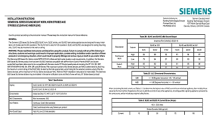
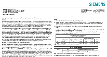
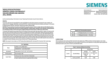
INSTALLATION INSTRUCTIONS SL SERIES 2 WIRE FIELD SELECTABLE STROBE AND HORN STROBE APPLIANCE MOUNT CLEAR AND AMBER LENS this product according to this instruction manual Please keep this instruction manual for future reference Siemens LED based SL Series SLHW horn SLSW strobe and SLHSW horn strobe appliances are designed for easy installation All are for 24V operation The SLHW horn is also for 12V operation SLSW and SLHSW are for wall mount only SLHW can be wall or mounted Please read these instructions carefully before using this product Failure to comply with any of the following instruc cautions and warnings could result in improper application candela setting installation and or operation of these products an emergency situation which could result in property damage and serious injury or death to you and or others Siemens LED based SL Series meets NFPA 2016 20 millisecond light pulse duration code requirements In addition the Siemens LED SL Series product line has been UL ULC listed as compatible with all Fire Alarm Control Panels FACP and accessories that have determined to be compatible with Siemens model ST Strobe based products including the ST CH SE SEF SET ST HS MTH S HQ STH ZR and ZH Series The maximum number of SL Series devices per NAC is determined by divid the maximum current rating the FACP NAC divided by the total appropriate current rating for the selected candela output of the SL Series devices with a maximum 105 SL Series devices per NAC Refer to FACP installation instructions for more detail The Siemens LED based SL Series strobes may installed in the same notification zone and field of view with any ST Strobe based product SLHSW UL 1971 ULC S526 16 SLSW A UL1638 ULC S526 16 1 Specifications SLHW UL 464 ULC S525 16 DRAW Use Only 0 C 49 C 32 F 120 F 93 R H Characteristics line resistance 35 Patterns Code 3 field selectable 3 synchronized when using Siemens sync protocol Sound Output HI Low LO field selectable Power or FWR 24V Regulated 16 to 33V All models or FWR 12V Regulated 8 to 17.5V SLHW only Candela 30 75 110cd field selectable is an on axis rating where the following applies effective candela rating per UL1971 Amber strobes are not to be used as a visual public mode alarm notification appliance AND HORN STROBE APPLIANCES LED based SL Series Multi Candela Strobes can provide a non synchronized strobe appliance when connected directly to a Fire Control Panel FACP or provide a synchronized strobe appliance when used in conjunction with an FACP that incorporates the sync protocol a Dual Sync Module DSC or the Siemens Power Supply The Code 3 temporal pattern 1 2 second on 1 2 second off 1 2 second on 1 2 second off 1 2 second on 1 1 2 off and repeat is by ANSI and NFPA 72 for standard emergency evacuation signaling 2A SLHW and SLHSW dBA Sound Output dBA Per UL 464 3 at 12V and SLHSW at 24V 2B SLHW and SLHSW dBA Sound Output Per CAN ULC S525 16 at 12V and SLHSW at 24V Horn 3 Horn 2C ULC Directional Characteristics 35 Degrees horizontal 45 30 vertical 90 Degrees horizontal 90 vertical 3 SLSW and SLSW A Strobe Current Draw Amps Candela Settings cd Volts 4 SLHSW Horn Strobe Current Draw Amps Candela Settings cd Settings Volts Continuous Code 3 Continuous Code 3 Continuous Code 3 Continuous Code 3 Candela and Horn Setting will determine the current draw of the product calculating the total currents use Tables 3 5 to determine the highest value of RMS current for an individual appliance then multiply values by the total number of appliances Be sure to add the currents for any other appliances including audible signaling appliances by the same source and to include any required safety factors Canada LimitedBuilding Technologies Division1577 North Service Road EastOakville Ontario L6H 0H6 CanadaPN P85580 001ASiemens Industry Inc Building Technologies DivisionFlorham Park NJPN P85580 001Afirealarmresources com 5 SLHW Horn Current Draw Amps Volts Volts Settings Continuous Code 3 Continuous Code 3 Continuous Code 3 Continuous Code 3 These notification appliances are UL Listed as They are intended to be used with Fire Alarm Control Panels FACPs notification circuits are UL Listed as Refer to the FACP instructions or the Siemens Strobe Compatibility Data Sheet 315 096363 for special application and strobe synchronization compatibility These appliances were tested to the regulated voltage limits of 16.0 33.0 Volts for 24 volt models and 8.0 17.5 Volts for 12 volt models filtered DC for the 12 volt range and either filtered DC or unfiltered DC for the 24 volt range voltage Do not apply voltage outside of this Check the minimum and maximum output of the power supply and standby battery and subtract the voltage drop from the circuit resistance to determine the applied voltage to the strobes The maximum wire impedance between strobes shall not exceed 35 Strobes are not designed to be used on coded systems in which the applied voltage is cycled on and off Make sure that the total rms current required by all appliances that are connected to the system primary and secondary power Notification Appliance Circuit NAC sync module DSC sync modules or Siemens power supplies does not exceed the power rated capacity or the current ratings of any fuses on the circuits to which these appliances are wired WARNING Overloading power sources or exceeding fuse ratings could result in loss of power and failure to alert occupants an emergency which could result in property damage and serious injury or death to you and or others OUTPUT Figure 2 LED Strobe Wiring 1 SLHSW SLSW and SLSW A Expected Light Output SETTINGS AND MOUNTING 3 Wire Connection Figure 4 Candela Selector All strobe appliances have in out wiring terminals that accept two 12 to 18 American Wire Gauge AWG wires at each screw terminal leads 3 8 inches and connect to screw terminals Break all in out wire runs on supervised circuits to ensure integrity of circuit supervision as shown in Figure 3 The polarity shown in 2 the wiring diagram is for the operation of the appliances The polarity is reversed by the FACP during supervision Wiring method shall be in accordance with CSA C22.1 Canadian Electrical Code Part 1 Safety Standard for Electrical Do not fully back out terminal screws The SLHSW and SLHW are factory set for the most common application of High dB and Code 3 The SLHSW and SLSW are set 15 candela Candela settings are shown in Figure 4