Siemens SLS, SLSPS – Wall-Mount Speaker and LED Speaker Strobes Notification Appliances, Installation Instructions

File Preview
Click below to download for free
Click below to download for free
File Data
| Name | siemens-sls-slsps-wall-mount-speaker-and-led-speaker-strobes-notification-appliances-installation-instructions-3518629407.pdf |
|---|---|
| Type | |
| Size | 1.32 MB |
| Downloads |
Text Preview
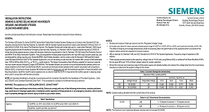
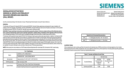
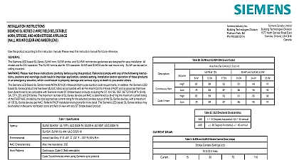
INSTALLATION INSTRUCTIONS SL SERIES WALL MOUNT HIGH FIDELITY AND SPEAKER STROBES AND CLEAR LENS this product according to this instruction manual Please keep this instruction manual for future reference SLSPW and SLSPSW Series High Fidelity Multi Candela Speaker Strobes are UL Listed under Standard 1971 for Signaling Devices for Hearing Impaired UL Standard 1480 for Speaker Appliances and ULC Listed under Standard CAN ULC S541 07 and CAN ULC S526 16 indoor Fire Protective Service The Speaker Strobes with amber lens are UL Listed under Standard 1638 Visual Signalling Appliance for Mode Emergency General Utility Signaling and ULC S526 16 Amber lens strobe appliances also comply with the polar distribution in the UL Standard 1971 for Indoor Fire Protection Service and NFPA 72 for Mass Notification Systems SLSPW and SLSPSW Series High Fidelity Multi Candela Speaker Strobes are designed for multiple power requirements with high dBA at each power tap Series SLSPW Speakers are UL Listed under UL Standard 1480 and ULC Listed under Standard CAN ULC for Speaker Appliances All models offer a choice of field selectable taps 1 8W to 2W for either 25.0 VRMS or 70.0 VRMS audio sys SLSPW and SLSPSW series speakers are UL rated to meet the NFPA 72 requirement for 520Hz signals in sleeping areas when used in with Siemens audio products The design incorporates a high efficiency speaker for maximum output at minimum power across a range of 300 8000Hz The Speaker Strobes can provide non synchronized strobe operation when connected directly to a Fire Alarm Panel FACP or provide synchronized strobe operation when used in conjunction with a Dual Sync Module DSC or Siemeens Supplies All models are Listed for indoor use only with the backboxes specified in these instructions see Mounting Options All Canadian Installations should be in accordance with the Canadian Standard for the Installation of Fire Alarm Systems CAN and Canadian Electrical Code Part 1 Final acceptance is subject to Authorities Having Jurisdiction This appliance is a ALARM DEVICE DO NOT PAINT Please read these instructions carefully Failure to comply with any of the following instructions cautions and warn could result in improper application installation and or operation of these products in an emergency situation which could in property damage and serious injury or death to you and or others Siemens LED based SL Series meets NFPA 2016 20 millisecond light pulse duration code requirements In addition the Siemens LED SL Series product line has been UL ULC listed as compatible with all Fire Alarm Control Panels FACP and accessories that have determined to be compatible with Siemens model ST Strobe based products including the ST CH SE SEF SET ST HS MTH S HQ STH ZR and ZH Series The maximum number of SL Series devices per NAC is determined by divid the maximum current rating the FACP NAC divided by the total appropriate current rating for the selected candela output of the SL Series devices with a maximum 105 SL Series devices per NAC Refer to FACP installation instructions for more detail The Siemens LED based SL Series strobes may installed in the same notification zone and field of view with any ST Strobe based product 1 Specifications SLSPSW UL 1971 ULC S526 16 SLSPSW A UL1638 ULC S526 16 Use Only 0 C 49 C 32 F 120 F 93 R H SLSPW UL1480 UL S541 07 Characteristics line resistance 35 power to 2W Power DC or FWR 24V Regulated 16 to 33V All models 25V to 70V Audio Candela 30 75 110cd field selectable is an on axis rating where the following applies effective candela rating per UL1971 Amber strobes are not to be used as a visual public mode alarm notification appliance 2 UL ULC Listed Speaker Models and Ratings at 10 Feet Rated Watts Per UL 1480 dBA CAN ULC S541 07 Strobes will produce 1 flash per second over the Voltage range All models are Listed for indoor use with a temperature range of 32 to 120 0 to 49 and maximum humidity of 93 RH effect of shipping and storage temperatures shall not adversely affect the performance of the appliance when it is stored in the cartons and is not subjected to misuse or abuse dBA is rated per UL Standard 1480 and ULC Standard ULC S541 07 for Speaker Appliances Frequency range of speakers is 300 These appliances were tested to the operating voltage limits of 16 33 volts using Filtered DC or unfiltered Full Wave Rectified FWR not apply 80 and 110 of these voltage values for system operation Check the minimum and maximum output of the power supply and standby battery and subtract the voltage drop from the circuit wiring to determine the applied voltage to the strobes 3 Current Ratings for Strobe Only RMS Current AMPS Range Voltage Candela setting will determine the current draw of the product and SLSPSW A 4 ULC Directional Characteristics 75 degrees horizontal 70 degrees vertical 90 degrees horizontal 90 degrees vertical The maximum wire impedance between strobes shall not exceed 35 OHMS Speaker Strobes are not designed to be used on coded systems in which the applied voltage is cycled on and off Make sure that the total RMS current required by all appliances that are connected to the system primary and secondary power NAC Circuits DSC Sync Modules or Siemens Power Supplies do not exceed the power sources rated capacity or the current of any fuses on the circuits to which these appliances are wired Overloading power sources or exceeding fuse ratings could result in loss of power and failure to alert occupants dur an emergency calculating the total currents use Table 2 to determine the highest value of Current for an individual strobe across the ex operating voltage range of the strobe then multiply these values by the total number of strobes be sure to add the currents for any appliances including audible signaling appliances powered by the same source and include any required safety factors the peak current exceeds the power supplies peak capacity the output voltage provided by the power supplies may drop below the listed range of the appliances connected to the supply and the voltage may not recover in some types of power supplies For example an power supply that lacks filtering at its output stage either via lack of capacitance and or lack of battery backup across the output exhibit this characteristic INFORMATION 1.5 blocking capacitor for DC supervision of audio lines by the FACP is factory wired in series with the speaker input Supervision volt must not exceed 33 volts DC SLSPSW Speaker Strobe models have in out wiring terminals that accept two 12 to 18 American Wire Gauge AWG wires at each terminal Strip leads 3 8 inches and connect to screw terminals Break all in out wire runs on supervised circuits to assure integrity of circuit supervision as shown in Figure 2 The polarity shown in the diagrams is for operation of the appliances Connect speaker wires to common and positive of terminal block and select the power tap terminal for 1 8W 1 4W 1 2W 1W or 2W or 70V as required see Figures 1 2 3,4 and Table 4 Each doubling of rated Watts increases sound output by 3 dBA Using the slide switch shown in Figure 3 select voltage and wattage as shown in Table 4 below Each letter corresponds to a position of the located on the printed circuit board to Sync Module instruction sheets DSC Siemens PN 315 545222 11 or Siemens Power Supplies for additional information The following figures show the maximum number of field wires conductors that can enter the backbox used with each mounting option If these are exceeded there may be insufficient space in the backbox to accommodate the field wires and stresses from the wires could damage the product Canada LimitedBuilding Technologies Division1577 North Service Road EastOakville Ontario L6H 0H6 CanadaPN P85583 001ASiemens Industry Inc Building Technologies DivisionFlorham Park NJPN P85583 001Afirealarmresources com Always operate audio amplifiers and speakers within their specified ratings Excessive input may distort sound quality and may audio equipment Improper input voltage can damage speaker If distortion is heard check for clipping of the audio appliance with an and reduce the amplifier input level or gain level to elim