Siemens SRC-8 Addressable 8-Output Relay Module, Installation Instructions

File Preview
Click below to download for free
Click below to download for free
File Data
| Name | siemens-src-8-addressable-8-output-relay-module-installation-instructions-0951462387.pdf |
|---|---|
| Type | |
| Size | 783.17 KB |
| Downloads |
Text Preview
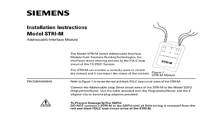
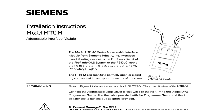
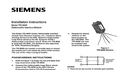
Installation Instructions SRC 8 8 Output Relay Module Model SRC 8 module from Siemens Inc used with the SXL EX System is 8 Output Programmable Relay Module that eight Form C relays Terminal Block 9 Figure 1 below provides a connection to on the Main Board for a 24V regulated and power supply Terminal blocks 1 8 the eight Form C relays the green LED labeled DS1 on the right side of the module is on it indicates that module is active all System power before first battery and then AC power up connect the AC first then the battery a New SXL EX System to Figure 2 the SRC 8 in the upper right hand of the EN SX enclosure by following the listed below SRC 8 causes a trouble on the display when any of the following three conditions the four 6 32 x 1 2 standoffs over the studs in the upper right hand corner of SXL EX enclosure as shown in Figure 2 There is a short on the data line Place the SRC 8 board over the four in the upper right hand portion of EN SX enclosure Using the four 6 32 provided fasten the SRC 8 board to standoffs No SRC 8 module is connected to the though there is an address for the in the System An SRC 8 module is connected to the but there is no address for it in the 1 2 3 4 5 6 7 8 1 Module 2 an SRC 8 Industry Inc Technologies Division Park NJ 315 092968 10 Building Technologies Ltd Safety Security Products Kenview Boulevard Ontario 5E4 Canada an Existing SXL System to Figure 3 place the SRC 8 on the Main Board of an system first remove the existing Display and its cover by following the steps below Remove the Display Cover from the Display as shown in Figure 3 Discard its top standoffs Unplug the ribbon cable from the Display at jumper JP4 on the Main Board 3 Remove the Display Board from the SXL Board by unscrewing the four 6 32 and setting them to one side Remove and discard the two standoffs that supporting the two upper corners of Display Board Next install the SRC 8 by using the four 6 x 1 7 8 standoffs the 6 32 screw and the 15 16 standoffs provided as follows Fasten the 1 7 8 nylon standoff provided to back of the upper left hand corner of SRC 8 with the screw provided Remove the screw from the upper right corner of the Main board Screw another long standoff to the upper corner of the Main board Screw the last two long standoffs provided the Main board as shown in Figure 3 Place the SRC 8 module on the standoffs Use the screw removed from the Main to secure the upper right hand of the SRC 8 board to the Main 3 in an Existing System Fasten the two short standoffs remaining to bottom two corners of the SRC 8 board are supports for the Display Board Once the SRC 8 is in place re install the Board by reversing Steps 1 3 above Program Level 9 to program the System to the SRC 8 module and refer to the Manual P N 315 095997 Program 5 for programming the relay output matrix To enter the System Press the RESET and DRILL keys at same time Enter your password Refer to Enter under PROGRAM MODE in Manual Press the SILENCE key to confirm the for the system An A should display in the 7 segment an F appears repeat the process until A appears To enter the Program Mode Press the ACK key once Note that a P displays in the 7 segment Be sure the PROGRAM TEST LED is lit To select the desired Program Mode level To select Program Level 9 press the button 9 times Press SILENCE To program the SRC 8 Note the top zone status LEDs on the board If the top red LED is on the SRC 8 is and sublevel 1 appears in display If the top red LED is off the SRC 8 is activated Press the DRILL key to toggle between activated and OFF de activated desired To exit the system Press the ACK key until an L appears the display Press SILENCE to exit the program Characteristics 18 mA 26mA per relay Characteristics Form C Relays at 30 VDC and 120 VAC resistive only to Figure 4 to Figure 4 below to wire the SRC 8 into SXL EX System wiring for the Form C relay circuits from blocks 1 8 is also shown in Figure 4 information on programming the relays on SRC 8 refer to the SXL EX Manual P N CALCULATIONS backup is required for the SRC 8 To the size battery you need use the calculation table in the SXL EX Manual 315 095997 The SXL EX Control Panel meets NFPA 72 Local System requirements All wiring must be in accordance with NFPA 70 Form C relay contacts are shown de energized They are suitable for resistive load only Refer to the Battery Calculations in the manual to determine battery needs Minimum 18AWG wire to all field connections C 1 C 2 C 3 C 4 C 5 C 6 C 7 C 8 SXL EX BOARD 4 AND NEGATIVE FAULT DETECTED 20K FOR TERMINALS ON TB9 4 the SRC 8 Industry Inc Technologies Division Park NJ 315 092968 10 Building Technologies Ltd Safety Security Products Kenview Boulevard Ontario 5E4 Canada