Siemens SSD-C-REM Remote System Status Display with Control, Installation Instructions
File Preview
Click below to download for free
Click below to download for free
File Data
| Name | siemens-ssd-c-rem-remote-system-status-display-with-control-installation-instructions-7496852013.pdf |
|---|---|
| Type | |
| Size | 743.98 KB |
| Downloads |
Text Preview
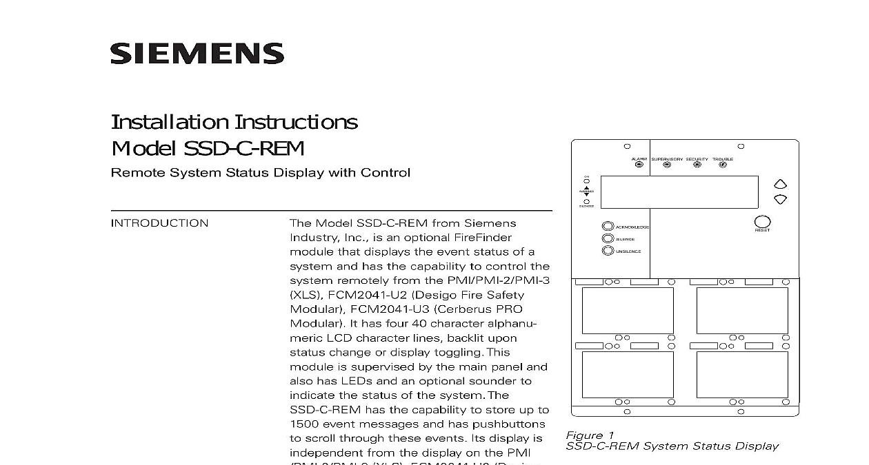
Installation Instructions SSD C REM System Status Display with Control Model SSD C REM from Siemens Inc is an optional FireFinder that displays the event status of a and has the capability to control the remotely from the PMI PMI 2 PMI 3 FCM2041 U2 Desigo Fire Safety FCM2041 U3 Cerberus PRO It has four 40 character alphanu LCD character lines backlit upon change or display toggling This is supervised by the main panel and has LEDs and an optional sounder to the status of the system The has the capability to store up to event messages and has pushbuttons scroll through these events Its display is from the display on the PMI XLS FCM2041 U2 Desigo Safety Modular FCM2041 U3 Cerberus PRO Modular During the SSD C REM power up the SSD C REM is configured in Display only mode 1 System Status Display following items are supplied with the SSD C REM nuts to mount the housing to the CAB1 2 3 or REMBOX2 4 P N 555 134828 for connection to an RNI requires RNI Rev 2 or higher SSD C REM has six LEDs and a sounder to indicate the status of the fire alarm The LCD indicates the state of a specific event The SSD C REM also has push that allow the user to scroll through the events list and or take control of the SSD C REM can be used in two different vectoring applications No Vectoring Queue Vectoring Refer to the Programming section on page 7 for information on the system the SSD C REM is used in a No Vectoring application all events that occur in system are displayed on the SSD C REM If the SSD C REM is configured with Control it can take full control of the system Acknowledge events Silence Audibles and Reset the system 315 034773 7 Inc Inc Inc Industry Inc Inc TTTTTececececechnologies Di Di Di Division Di Vectoring displays only the specific event type such as Alarm only Trouble etc and is set by deselecting any Display type in the Zeus Programming Tool SSD C REM with System Control has control of the system as long as the system are the same event type for which it is configured Otherwise it responds as Only For example if the SSD C REM is configured as an ALARM only display there are only alarms present in the system then the SSD C REM will have full control However if for the same SSD C REM there are alarms and troubles the system then pressing a control push button Acknowledge Silence Unsilence Reset on the SSD C REM will have no effect on the system The corresponding of the queue type not vectored will activate momentarily to indicate to the user an event of a different queue is present in the system and Indicators front panel of the SSD C REM contains 6 LEDs 1 LCD display up and down buttons and Acknowledge Silence Unsilence and Reset buttons as in Figure 1 LEDs and their functions are defined as follows OFF Indicates that there is no event in the system flashing Indicates that at least ONE event is unacknowledged steady Indicates that ALL alarm have been acknowledged OFF Indicates that there is no event in the system flashing Indicates that at least ONE event is unacknowledged steady Indicates that ALL supervi events have been acknowledged OFF Indicates that there is no event in the system flashing Indicates that at least ONE event is unacknowledged steady Indicates that ALL security have been acknowledged OFF Indicates that there is no event in the system flashing Indicates that at least ONE event is unacknowledged steady Indicates that ALL trouble have been acknowledged Industry Inc Technologies Division 315 034773 7 ON SILENCED OFF Indicates that NACs are in mode or that ALL NACs have been silenced steady Indicates that at least ONE has been activated OFF Indicates that NACs are in mode or that there is at least activated NAC in the system steady Indicates that previously NACs have been silenced both AUDIBLES ON and AUDIBLES SILENCED LEDs are in the OFF state it that all NACs in the system are in supervisory mode Sounder operates as follows OFF Indicates that the system is in supervi mode or all events in the system have been or that a push button has been pressed Indicates that at least one unacknowl alarm is present in the system Indicates that at least one unacknowl non alarm security supervisory or trouble is present in the system and that there are no events present or all alarm events have been the SOUNDER DISABLE option is selected in the Zeus Programming Tool the remains OFF regardless of the status of the system In systems where the selected is Canada the sounder disable option is not available pushbuttons and their functions are defined as follows ARROW Supervisory Mode Activates the backlight for 10 minutes Event Is Displayed Displays the with the next higher priority See 2 for more information about the between U S and Canada Supervisory Mode Activates the backlight for 10 minutes Event Is Displayed Displays the with the next lower priority See 2 for more information about the between U S and Canada ARROW Industry Inc Technologies Division 315 034773 7 2 Priority events are displayed one at a time and cycle through a circular list once the most event message is reached See Figure 2 RECENT RECENT RECENT RECENT Supervisory Mode Activates LCD backlight for minutes Event Is Displayed Acknowledges the unac queue and or events with the highest If no events are present it is ignored Supervisory Mode Activates LCD backlight for minutes Event Is Displayed Silences all activated NACs when all alarm events are acknowl If NACs are already silenced it is ignored Supervisory Mode Activates LCD backlight for minutes Event Is Displayed Reactivates all silenceable that were previously silenced If NACs are active it is ignored Supervisory Mode Activates LCD backlight for minutes Event Is Displayed Resets the system provided all events are acknowledged and all silenceable are silenced If system is already reset it is See Figure 3 LCD backlight activates for 10 minutes when an occurs or when a push button is pressed Industry Inc Technologies Division 315 034773 7 Mode 1 Current date and time 2 Custom message and system ID 3 Custom message and system ID 4 Blank Event Mode 1 Event Status module device address date and of the event 2 Custom message for the module device 3 Event category or trouble type sequence of the event 4 Total number of Alarms Supervisory Security Trouble events in the system or vectored to SSD C REM message system id 1 message system id 2 15 2002 04 10 52pm 3 45 message for this alarm 16 2002 04 15 25pm of 200 3 LCD Supervisory Mode Top and Active Event Mode Bottom Industry Inc Technologies Division 315 034773 7 following components must be set prior to installing the SSD C REM housing to the SSD C REM mounting plate Refer to Figure 4 Set to ON if the SSD C REM is the end of the PAIR A wiring Style 4 only Option Select DIP Switch Set to OFF Not Used Set to OFF Not Used Set to OFF Not Used S3 5 6 5 6 5 6 4